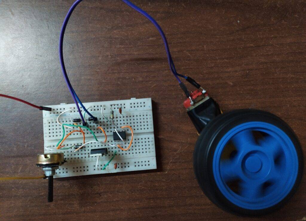
Hey techies, welcome back to Techatronic. Are you searching for a DC motor speed controller circuit? If yes then read this article carefully and learn to make your own 555 PWM motor speed control circuit by using 555 timer IC. A 555 timer IC is used to obtain perfect delay signals.it is very easy to control the speed of the motor using the 555 PWM Generator principle.
Table of Contents
Introduction
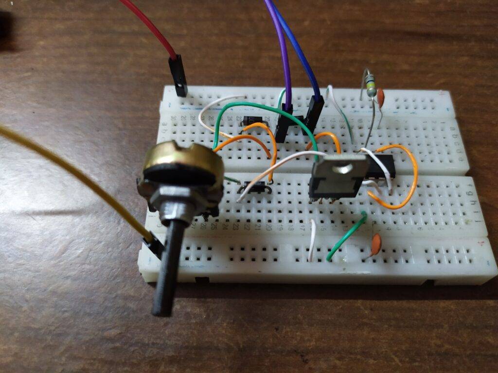
In this PWM generator using 555 timer project, we are going to use a breadboard for making the circuit but if you want you can use a PCB board and solder the components. The detailed circuit is given below and we are also sharing the images of the circuit so it is easy to make. You can also check the cell phone signal jammer circuit using a 555 timer made by us.

we have a huge list of the 555 timer PWM projects. so if you want to learn and make your 555 timer project you can bookmark our website. still, if you have any doubt you can ask us in the comment section. Also, check out more projects on basic electronics.
555 timer pwm Working.
The circuit we made is useful for controlling the speed of a DC motor. It generates a PWM (pulse width modulation) signal continuously with different duty cycles so that the speed of the motor can vary.
if you know this thing 555 is used to generate the PWM. that’s why most of the students in electronics search once 555 PWM generator. You can control the speed of the motor by rotating the potentiometer. Check out the LED flasher circuit made by us using 555 IC.
The 555 timer ic is known to make the oscillation which results in generating the square wave. and with the help of the 555 PWM circuit, we will modify the width of the pulse by using a potentiometer. when you rotate this potentiometer the speed of the motor will change according to the potentiometer.
the potentiometer is a variable resistor. so when you rotate this potentiometer the resistance value will change the width of the pulse also be modified. 555 IC working with the resistor and capacitor. so , it depends on the external resistor so,555 PWM motor speed control by using the potentiometer is very easy to make.
Components Required
- 555 timer IC
- Small connecting wires and a breadboard
- Two 100 nF capacitors
- 1K-ohm resistor
- tip 122
- DC motor and a 5-volts supply
- Three in4007 diodes
- 100K potentiometer
PWM dc motor speed controller Circuit Diagram

- Place a 555 timer IC in the middle of the breadboard.
- Then connect the power supply to the positive and negative rails of the breadboard.
- Attach pin 1 of the IC to the negative rail and pin 8 to the positive rail of the breadboard.
- Place the tip-122 MOSFET and join its emitter pin to the positive rail and base pin with the positive leg of the diode.
- Attach the negative leg of the same diode with a pin of the DC motor.
- Connect another pin of the DC motor with the base pin of the tip-122 MOSFET.
- Take a 100K ohm potentiometer and connect its middle leg with the middle pin of the MOSFET.
- Join the positive leg of a diode with the negative leg of another diode and attach the node to the positive rail of the breadboard.
- Connect the negative leg of the first diode with the third pin of the potentiometer and the positive leg with the negative rail of the breadboard.
- Attach the first pin of the potentiometer with the negative rail and the third pin with pin number 3 of the 555 IC. J
- oin a 100 nF capacitor between pin 5 and negative rail.
- Similarly between pin 1 and 2. Connect a 1K ohm resistor between pin 7 and positive rail.
Join pins 2 and 6, 4 and 8 with each other as given in the diagram.
Final Look of the Project
Connect the positive and negative wires of the power supply to the breadboard and the PWM dc motor speed controller circuit is ready to use.

We hope that you understand the project completely and now try to make it once. While making this if you face any difficulties, feel free to use the comments section given below. You can also check tutorials on Arduino and Raspberry pi.
HAPPY LEARNING!
Latest 555 timer projects
Led Chaser Circuit Using 4017 IC
Fastest Finger First Circuit Using 555 timer IC