
Hey geeks, hope you are doing fine. In this article, we are going to discuss a very interesting and trending project that is automation using a telegram bot. For sending and receiving the data with the telegram application we are using a NodeMCU esp8266 IoT development board. Check out the pulse oximeter using NodeMCU made by us. Like the other chatting apps telegram is a social media platform too. In this project, we are going to control three LEDs with the help of a telegram bot. You can also check out more cool projects on IoT.

What is a Telegram Bot
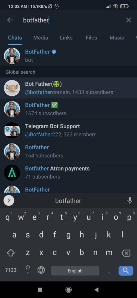
First of all, download the telegram application and make an account on it. Then go to the search bar and search for botfather and open the account with a blue tick. For your reference, we are sharing the screenshots from the application.
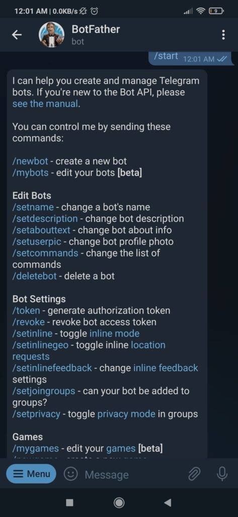
Now click on start to initiate the bot and see the menu.

There are many options in front of you. Click on the new bot to create a new project. Later you can find the bots that you have made by clicking on my bots. You can also choose the commands as per your requirements after you create a new bot.
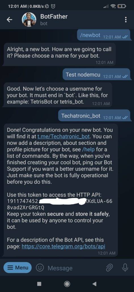
Now it will ask you to give a name and then a username to the bot you want to make. Please go for a unique name or else it will not accept it. For the username use _bot at last as shown below. After this, you will get a unique token id which you have to copy. Then paste this id in the code. Use the link given in the messages to open your bot.
After opening type start and then it will reply to you with the message as shown below in the screenshot. Now send the commands on the app such as light on/off as per your need and the LEDs are turning on and off according to your actions.

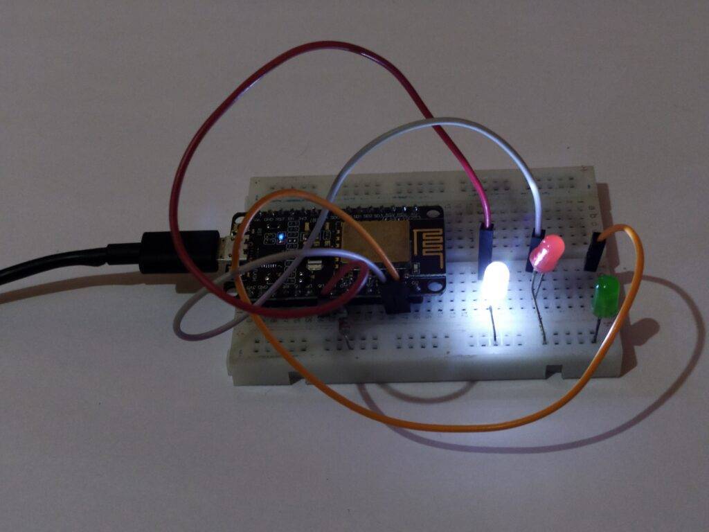
When you type RED LIGHT ON the red LED will turn on as shown below.
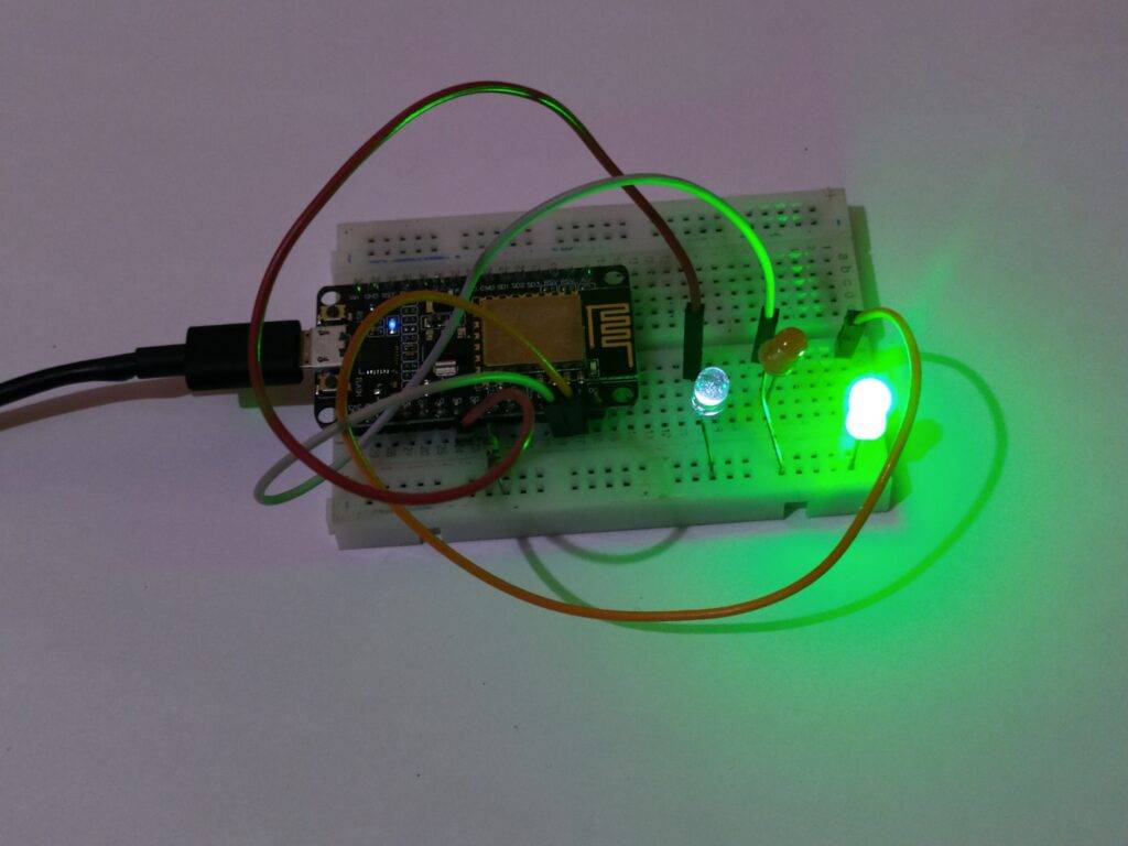
when you type GREEN LIGHT ON the green LED will turn on.
And if you type WHITE LIGHT ON the white LED will turn on.
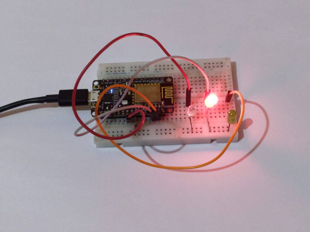
Components Required
- NodeMCU esp8266
- Three LEDs of different colors
- 220-ohm resistor
- Jumper wires and a breadboard
- USB cable for uploading the code
telegram bot automation Circuit Diagram

| Arduino | LED B | LED G | LED R | 220 Ohm Resistor |
| D1 Pin | Anode Pin | |||
| D2 Pin | Anode Pin | |||
| D6 Pin | Anode Pin | |||
| GND | Terminal 1 | |||
| Cathode Pin | Cathode Pin | Cathode Pin | Terminal 2 |
NodeMCU digital-1 pin -> positive leg of the first LED
NodeMCU digital-2 pin -> positive leg of the second LED
NodeMCU digital-6 pin -> positive leg of the third LED
NodeMCU GND pin -> negative leg of all the LEDs via a 220-ohm resistor
telegram bot Code
NOTE: Please upload the code which is given below to the NodeMCU but before that install <CTBot.h> library to the IDE software. Check how to install a zip library to the Arduino IDE.
 //Techatronic.com
 #include "CTBot.h"
 CTBot myBot;
 String ssid = "xxxxxxxxxxxx";   // REPLACE SSID WITH YOUR WIFI SSID
 String pass = "xxxxxxxxxxxx"; // REPLACE Password YOUR WIFI PASSWORD, IF ANY
 String token = "---------------------------------------------------";  // REPLACE Token WITH YOUR TELEGRAM BOT TOKEN
 uint8_t greenled = 5;
 uint8_t redled = 4;
 uint8_t whiteled = 12;
 void setup() {
  // initialize the Serial
  Serial.begin(115200);
  Serial.println("Starting TelegramBot...");
  // connect the ESP8266 to the desired access point
  myBot.wifiConnect(ssid, pass);
  // set the telegram bot token
  myBot.setTelegramToken(token);
  // check if all things are ok
  if (myBot.testConnection())
   Serial.println("\ntestConnection OK");
  else
   Serial.println("\ntestConnection NOK");
  // set the pin connected to the LED to act as output pin
  pinMode(redled, OUTPUT);
  digitalWrite(redled, LOW);
  pinMode(greenled, OUTPUT);
  digitalWrite(greenled, LOW);
  pinMode(whiteled, OUTPUT);
  digitalWrite(whiteled, LOW);
 }
 void loop() {
  // a variable to store telegram message data
  TBMessage msg;
  // if there is an incoming message...
  if (myBot.getNewMessage(msg)) {
   if (msg.text.equalsIgnoreCase("RED LIGHT ON")) {       // if the received message is "LIGHT ON"...
    digitalWrite(redled, HIGH);                // turn on the LED
    myBot.sendMessage(msg.sender.id, "RED Light is now ON"); // notify the sender
   }
   else if (msg.text.equalsIgnoreCase("RED LIGHT OFF")) {    // if the received message is "LIGHT OFF"...
    digitalWrite(redled, LOW);               // turn off the led
    myBot.sendMessage(msg.sender.id, "RED Light is now OFF"); // notify the sender
   }
   else if (msg.text.equalsIgnoreCase("GREEN LIGHT ON")){
    digitalWrite(greenled, HIGH);                // turn on the LED
    myBot.sendMessage(msg.sender.id, "GREEN Light is now ON"); // notify the sender
   }
   else if (msg.text.equalsIgnoreCase("GREEN LIGHT OFF")){
    digitalWrite(greenled, LOW);               // turn off the led
    myBot.sendMessage(msg.sender.id, "GREEN Light is now OFF"); // notify the sender
   }
   else if (msg.text.equalsIgnoreCase("White LIGHT ON")){
    digitalWrite(whiteled, HIGH);                // turn on the LED
    myBot.sendMessage(msg.sender.id, "WHITE Light is now ON"); // notify the sender
   }
   else if (msg.text.equalsIgnoreCase("WHITE LIGHT OFF")){
    digitalWrite(whiteled, LOW);               // turn off the led
    myBot.sendMessage(msg.sender.id, "WHITE Light is now OFF"); // notify the sender
   }
   else {                          // otherwise...
    // generate the message for the sender
    String reply;
    reply = (String)"Welcome " + msg.sender.username + (String)". Try LIGHT ON or LIGHT OFF.";
    myBot.sendMessage(msg.sender.id, reply);       // and send it
   }
  }
  // wait 500 milliseconds
  delay(500);
 }
We hope that you like this project and if so then please try it by yourself once. Also, check tutorials on Arduino and Raspberry Pi. Feel free to use the comments section below to share your opinions and suggestions.