

Hey Friends, I’m here to discuss again an interesting and important article based on Raspberry Pi. Today we’re going to discuss Light Sensor Raspberry pi. The components for this project are very simple and are easily available in any market either online or offline. If you are starting coding with python or getting started with Raspberry Pi then make sure to visit my other Raspberry Pi articles to have a clear view of each function and module. So now without wasting any time let’s get started.
Table of Contents
LDR
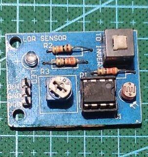
LDR Sensor is not another type of Resistor that reacts to the light nearby it. LDR is used in various projects which require tasks to be done based on the basis of the light in nearby surroundings. The construction is very simple for the LDR. To make an LDR a zigzag shape grove is over an insulating material(ceramic), inside this shape a photosensitive material like CdS, CdSe & PbS. These substances are reactive to light and upon getting exposed to light the photoelectric effect takes place.
The details phenomena are explained in my similar article on Pi PICO, which you can visit for more knowledge. The Light Sensor Raspberry pi is available in various shape sizes and colors of light-sensitive material depending on the range of resistance it can reach. For my convenience, I’m using the very basic one which reaches a range of 0KOhm to 1MOhm.
Material Required
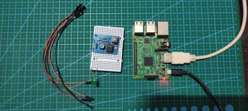
- Raspberry Pi (with keyboard, Mouse, and Display)
- LDR Module
- Breadboard
- Jumper wires
| S.No | Component Required | Quantity | Buy Link |
| 1. | Raspberry pi 3B+ | 1 | BUY LINK |
| 2. | Raspberry pi Cable | 1 | BUY LINK |
| 3 | USB Mouse & Keyboard | 1 | |
| 4. | Raspberry pi Combo | 1 | BUY LINK |
| 5. | Jumper Wire | 40 | BUY LINK |
| 6. | Breadboard | 1 | BUY LINK |
| 7. | Power supply | 1 | BUY LINK |
| 8. | LED | 1 | BUY LINK |
| 9. | 220 Ohm Resistor | 1 | BUY LINK |
| 10. | LDR Sensor | 1 | BUY LINK |
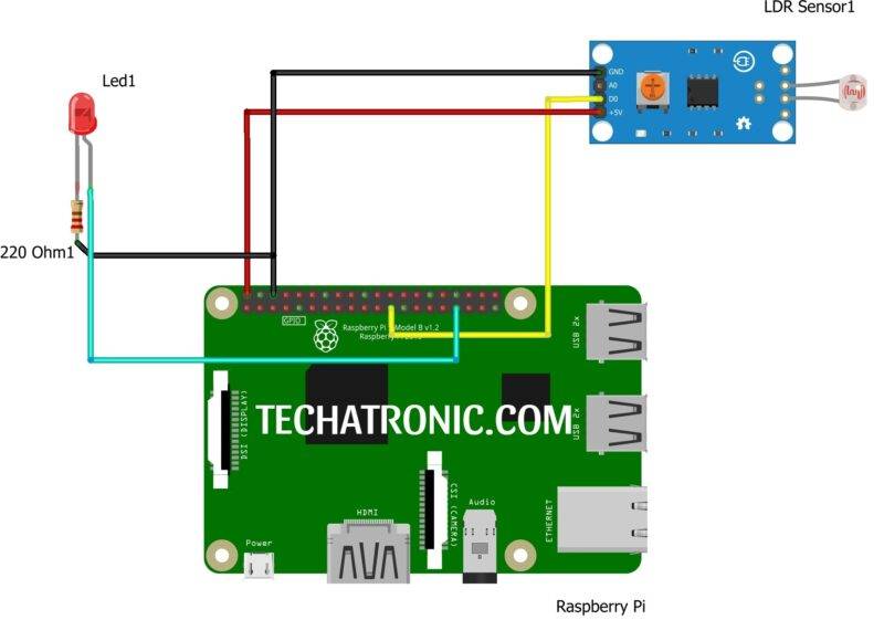
Light Sensor Raspberry pi Circuit Diagram
|
Raspberry PI |
LDR Sensor | |
|
GPIO 11 Pin |
D0 | |
|
+5V | +5 V, VCC | |
|
GND |
GND | |
|
Raspberry PI |
LED | 220-ohm Resistor |
|
GPIO 13 Pin |
Anode Terminal ( + ) |
|
|
GND |
|
Terminal 1 |
|
|
Cathode Terminal ( – ) |
Terminal 2 |
LDR Module OUT Pin to Board pin number 11 & LED to pin number 13 of Raspberry Pi according to BOARD numbering
Light Sensor Raspberry pi Code
Explanation
At the beginning of the code, we’ve included or imported some basic modules which are required for the program to work efficiently. RPI & time modules are required for defining the pin and performing various functions on it and time for making time-related function work.
Further, we define pin mode to BOARD. You can set it to either BCM or BOARD according to your convenience. in this Light Sensor Raspberry pi I prefer board as it is easy to locate pins. Next, we define a while loop inside which we put our main code in the try and except method to make the code work until the Keyboard Interrupt arrives.
Code
 import RPi.GPIO as gp
 from time import sleep
 gp.setmode(gp.BOARD)
 gp.setup(11,gp.IN)
 gp.setup(13,gp.OUT)
 while True:
   try:
     if gp.input(11)==1:
       gp.output(13,gp.HIGH)
     elif gp.input(11)==0:
       gp.output(13,gp.LOW)
   except KeyboardInterrupt:
     gp.cleanup()
     break
With this, we’ve completed our article on LDR RPI. If you come through any problem then ask me below, I’ll answer all of them.