
Table of Contents
Introduction
Hey geeks, welcome back to Techatronic. In this article, we are going to make a heart beat sensor using Arduino UNO. You can find the BPM monitors on your smartwatches and hospitals. Just like them, we tried to make it using Arduino and pulse sensor.
We also add a 16×2 LCD display on which you can see the values calculated by the pulse sensor. You can also check more projects on Arduino and IoT made by us. Please make the circuit as given in the diagram and then upload the code to the Arduino.

Description
- If you are not familiar with the working of a pulse sensor with Arduino then please check it here.
- You just have to put your finger on the sensor and the Arduino will automatically calculate your heartbeat rate.
- For displaying the readings we are using a 16×2 LCD here.
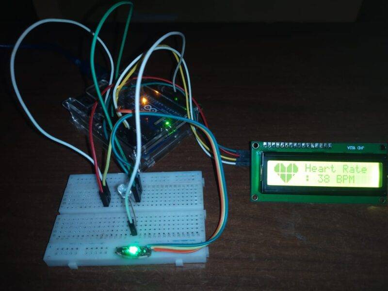
- At first a message ‘put your finger here’ is displayed and when you put your finger on it then it starts displaying BPM with a heart icon.
- The LED will turn on and start flashing.
- You can also check the heart rate sensor using Arduino made by us.
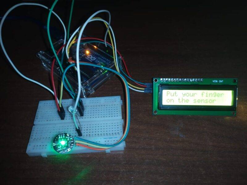
Final Image of heart beat sensor with Arduino

Components Required
| Arduino uno | BUY LINK |
| pulse sensor | BUY LINK |
| LED | BUY LINK |
| 220 ohm resistor | BUY LINK |
| 12c module | BUY LINK |
| 16×2 LCD | BUY LINK |
| Jumper wires | BUY LINK |
| breadboard | BUY LINK |
| uno cable | BUY LINK |
Circuit for Heart Beat Sensor BPM Monitor
- Take a pulse sensor and connect its VCC pin with the 5 volt pin of the Arduino.
- Join the GND pin of the pulse sensor with the GND pin of the Arduino.
- Attach the OUT/signal pin of the heart beat sensor to the Analog-0 pin of the Arduino.
- Now take an LED and connect its positive leg with the digital-3 pin of the Arduino.
- Join the negative leg of the LED with the GND pin of the Arduino via a 220 ohm resistor.
- Then Connect the I2C module with the 16×2 LCD module.
- You can also check the interfacing of the I2C module with Arduino.
- Join the VCC pin of the I2C module with the 5 volt pin of the Arduino and the GND pin of the Arduino with the GND pin of the I2C module.
- Connect the SDA and SCK pins of the I2C module with the analog-4 and analog-5 pins of the Arduino as shown in the diagram.
- Make sure that the connections are correct and tight.
Code for Heart Beat Sensor BPM Monitor

| Arduino UNO | Pulse Sensor / heart beat sensor | |
| A0 Pin | OUT Pin | |
| VCC | VCC | |
| GND | GND | |
| Arduino UNO | I2C Module | |
| A4 Pin ( SDA ) | SDA Pin | |
| A5 Pin ( SCL ) | SCL Pin | |
| VCC | VCC | |
| GND | GND | |
| 16*2 LCD Display | I2C Module | |
| 16 Pin connect | 16 Pin connect | |
| Arduino UNO | LED | 220-ohm Resistor |
| 3 Pin | Anode Terminal | |
| GND | Terminal 1 | |
| Cathode Terminal | Terminal 2 |
NOTE: Please upload this code to the Arduino. You have to install <PulseSensorPlayground.h> and <LiquidCrystal_I2C.h> libraries first. If you don’t know how to add zip libraries to the Arduino IDE then go through it first.
//Techatronic.com
#define USE_ARDUINO_INTERRUPTS true //--> Set-up low-level interrupts for most acurate BPM math.
#include <PulseSensorPlayground.h> //--> Includes the PulseSensorPlayground Library.
#include <LiquidCrystal_I2C.h> //--> Includes the LiquidCrystal Library.
LiquidCrystal_I2C lcd(0x27,16,2);


const int PulseWire = 0; //--> PulseSensor PURPLE WIRE connected to ANALOG PIN 0
int LED_3 = 3; //--> LED to detect when the heart is beating. The LED is connected to PIN 3 on the Arduino UNO.
int Threshold = 550; //--> Determine which Signal to "count as a beat" and which to ignore.
                     //--> Use the "Gettting Started Project" to fine-tune Threshold Value beyond default setting.
                     //--> Otherwise leave the default "550" value.

byte heart1[8] = {B11111, B11111, B11111, B11111, B01111, B00111, B00011, B00001};
byte heart2[8] = {B00011, B00001, B00000, B00000, B00000, B00000, B00000, B00000};
byte heart3[8] = {B00011, B00111, B01111, B11111, B11111, B11111, B11111, B01111};
byte heart4[8] = {B11000, B11100, B11110, B11111, B11111, B11111, B11111, B11111};
byte heart5[8] = {B00011, B00111, B01111, B11111, B11111, B11111, B11111, B11111};
byte heart6[8] = {B11000, B11100, B11110, B11111, B11111, B11111, B11111, B11110};
byte heart7[8] = {B11000, B10000, B00000, B00000, B00000, B00000, B00000, B00000};
byte heart8[8] = {B11111, B11111, B11111, B11111, B11110, B11100, B11000, B10000};
//----------------------------------------

int Instructions_view = 500; //--> Variable for waiting time to display instructions on LCD.

PulseSensorPlayground pulseSensor; //--> Creates an instance of the PulseSensorPlayground object called "pulseSensor"

//--------------------------------------------------------------------------------void setup
void setup() {
  Serial.begin(9600);//--> Set's up Serial Communication at certain speed.
  lcd.begin(); //--> Initializes the interface to the LCD screen, and specifies the dimensions (width and height) of the display

  //----------------------------------------Create a custom character (glyph) for use on the LCD
  lcd.createChar(1, heart1);
  lcd.createChar(2, heart2);
  lcd.createChar(3, heart3);
  lcd.createChar(4, heart4);
  lcd.createChar(5, heart5);
  lcd.createChar(6, heart6);
  lcd.createChar(7, heart7);
  lcd.createChar(8, heart8);
  //----------------------------------------

  lcd.setCursor(0,0);
  lcd.print(" HeartBeat Rate ");
  lcd.setCursor(0,1);
  lcd.print("   Monitoring   ");

  //----------------------------------------Configure the PulseSensor object, by assigning our variables to it.
  pulseSensor.analogInput(PulseWire);
  pulseSensor.blinkOnPulse(LED_3); //--> auto-magically blink Arduino's LED with heartbeat.
  pulseSensor.setThreshold(Threshold);
  //----------------------------------------

  //----------------------------------------Double-check the "pulseSensor" object was created and "began" seeing a signal.
  if (pulseSensor.begin()) {
    Serial.println("We created a pulseSensor Object !"); //--> This prints one time at Arduino power-up,  or on Arduino reset.
  }
  //----------------------------------------

  delay(2000);
  lcd.clear();
}
//--------------------------------------------------------------------------------

//--------------------------------------------------------------------------------void loop
void loop() {
  int myBPM = pulseSensor.getBeatsPerMinute(); //--> Calls function on our pulseSensor object that returns BPM as an "int". "myBPM" hold this BPM value now.

  //----------------------------------------Condition if the Sensor does not detect the heart rate / the sensor is not touched.
  if (Instructions_view < 500) {
    Instructions_view++;
  }

  if (Instructions_view > 499) {
    lcd.setCursor(0,0);
    lcd.print("Put your finger ");
    lcd.setCursor(0,1);
    lcd.print("on the sensor   ");
    delay(1000);
    lcd.clear();
    delay(500);
  }
  //----------------------------------------

  //----------------------------------------Constantly test to see if "a beat happened".
  if (pulseSensor.sawStartOfBeat()) { //--> If test is "true", then the following conditions will be executed.
    Serial.println("♥  A HeartBeat Happened ! "); //--> Print a message "a heartbeat happened".
    Serial.print("BPM: "); //--> Print phrase "BPM: "
    Serial.println(myBPM); //--> Print the value inside of myBPM.

    //----------------------------------------Displays a "Heart" shape on the LCD.
    lcd.setCursor(1,1);
    lcd.write(byte(1));
    lcd.setCursor(0,1);
    lcd.write(byte(2));
    lcd.setCursor(0,0);
    lcd.write(byte(3));
    lcd.setCursor(1,0);
    lcd.write(byte(4));
    lcd.setCursor(2,0);
    lcd.write(byte(5));
    lcd.setCursor(3,0);
    lcd.write(byte(6));
    lcd.setCursor(3,1);
    lcd.write(byte(7));
    lcd.setCursor(2,1);
    lcd.write(byte(8));
    //----------------------------------------

    //----------------------------------------Displays the BPM value on the LCD.
    lcd.setCursor(5,0);
    lcd.print("Heart Rate");
    lcd.setCursor(5,1);
    lcd.print(": ");
    lcd.print(myBPM);
    lcd.print(" ");
    lcd.print("BPM     ");
    //----------------------------------------

    Instructions_view = 0;
  }
  //----------------------------------------

  delay(20); //--> considered best practice in a simple sketch.
}
//--------------------------------------------------------------------------------
//===============================================================================================
We hope that you liked this project and understand it’s working of heart beat sensor completely. If you have any doubts regarding this project then do let us know in the comments section given below. You can also check out more projects on Arduino projects, iot Projects and Raspberry Pi.
Also Check the related project of Heart beat sensor and Pulse sensor
Pulse Sensor Interfacing With Arduino | How Pulse Sensor works with Arduino
How to make Heart Rate Monitor
OLED Display With Arduino| SSD1306 OLED
Thanks for reading.