
Hello techies, welcome back to Techatronic. There are numerous ways to ward off mosquitoes. Some use domestic remedies, and some use mosquitoes repellants. But do you know we can also make a mosquito repellent using 555 timers with the help of 555 timer ic? So let’s start, in this project we are using a 555 ic to produce a high-frequency sound output to ward off the mosquitoes.
Table of Contents
Introduction
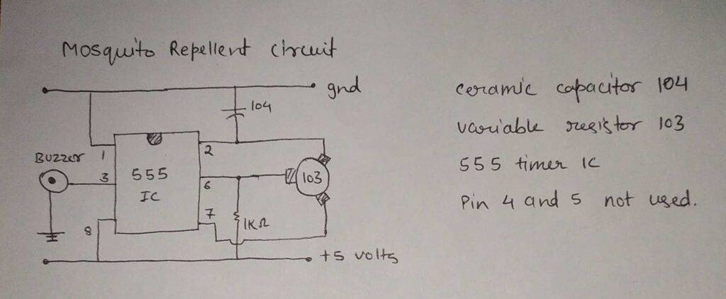
Also, do check out our projects on IoT and Basic electronics. The details of the working of the project and circuit diagram are given below. The preset that we are using is a 10K ohm (103) variable resistor. A variable resistor is used to vary the voltage and current in the circuit.
It has three pins from which the variable voltage can be obtained using a middle pin based on the voltage difference that is applied to the two other pins. Check the touchless water tap using Arduino made by us.
About the Project
The Mosquito repellent Using 555 timer generates high-frequency ultrasonic sound waves when the power is on. We are using a preset for adjusting the frequency of the generated sound. Use this circuit in your room for 10 to 15 minutes and you will notice that the mosquitoes will escape out of the room slowly.

Mosquitoes and similar insects can not bear this ultrasonic noise and try to go away from the source by this 555 timer project. We are preferring the breadboard for making the connections as it is safe to handle and you can replace the components easily as well. You can also use a PCB board and solder the components with each other.
Handel the soldering iron carefully. Connect the power supply to the circuit and adjust the variable resistor such that the buzzer starts making the ultrasonic sound. Check automatic college bell project using Arduino made by us.
Components Required
- ne555 timer ic
- 103 variable resistor
- Buzzer and 9 v0lts power supply
- Connecting wires and a breadboard
- 104 ceramic capacitor
- 1K-ohm resistor
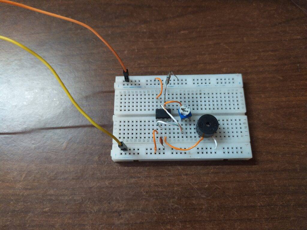
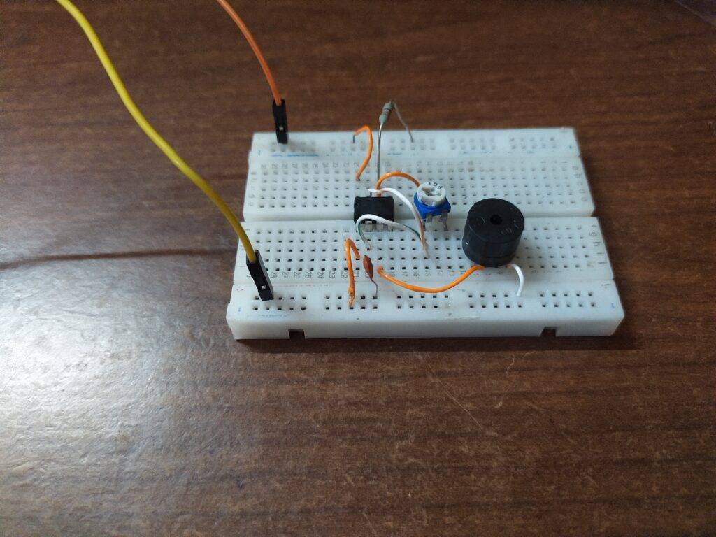
Mosquito repellent Using 555 Timer circuit
- Follow the given instructions carefully and make sure that the connections are proper and tight.
- Connect the 555 timer ic on the middle of the breadboard and join the positive wire of the battery with the positive rail.
- Join the negative wire of the battery with the negative rail of the breadboard.
- Now connect pin 1 of the ic with the negative rail and pin 8 with the positive rail.
- Attach pin 3 that is the output pin of the ic with the positive leg of the buzzer and the negative leg with the negative rail.
- Join pin 7 with the side pin of the variable resistor.
- Attach a ceramic capacitor between pin 2 of the ic and the negative rail.
- Connect pin 6 with the middle pin of the variable resistor and with positive rail also via a 1K-ohm resistor.
- At last join pin 2 with another side pin of the variable resistor.
We hope that you like this project and if so then please try to make it once. If you have any doubts or suggestions regarding this project then feel free to use the comments section below. Also, check our tutorials on Arduino and Raspberry Pi.
HAPPY LEARNING!
Latest 555 timer project
555 Timer Square Wave Generator | Astable Multivibrator
Fastest Finger First Circuit Using 555 timer IC