
Hey guys, welcome back to Techatronic. We are sure that you had studied logic gates if you are a student from a science background. In this article, we are going to make three different logic gates with the help of transistors. There are different types of logic gates from which some have one input and some have more number of inputs. In the logic gates circuits that we have made the inputs are taken through push buttons and the output is obtained using LEDs. You can check more interesting projects on this website.
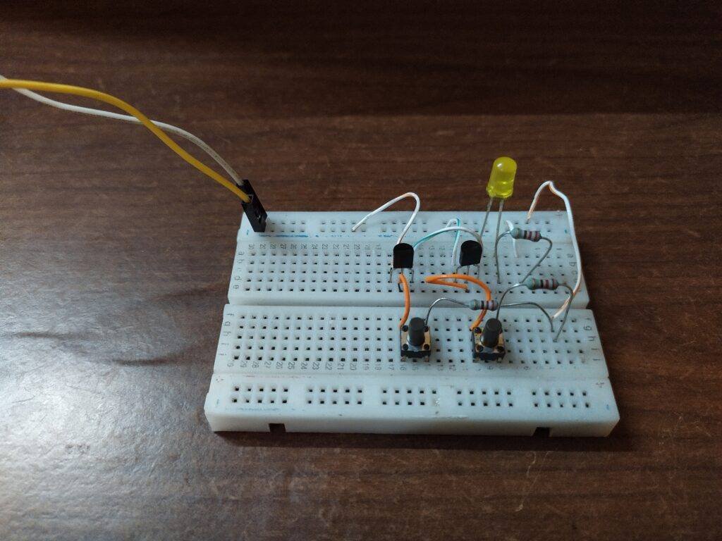
logic gates with transistors on hardware
Not Gate

In this gate, there is a single input and a single output. The not gate is also called an inverter because it inverts the given input signal. When the input is 0 the output is 1 and vice versa. You can see in the image that the LED glows when the button is in the off state.

AND Gate

This gate will take two inputs and generate one output based on the product of the two inputs. The output goes 1 only when both the inputs are 1. In the other three cases, the product of the inputs is 0 so the LED keeps off.


OR Gate
‘

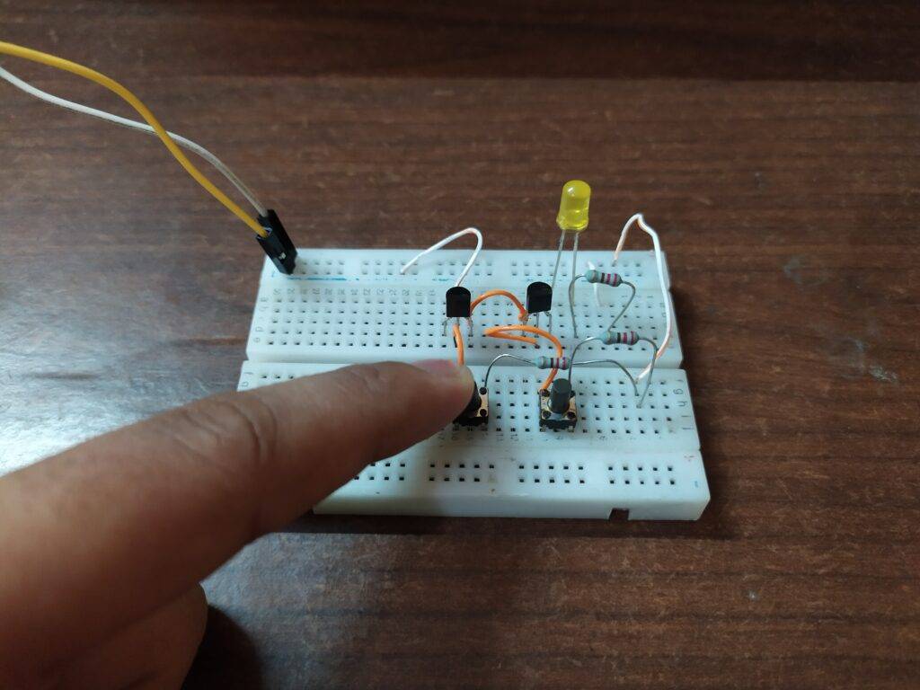
The generated output of this gate will depend on the sum of the two given inputs. In this, the output is 0 only for the first case when both of the inputs are 0. Else for the remaining three cases, the LED keeps glowing as the output is 1.


Components Required
| Two BC547 transistors | |
| Connecting wires | BUY LINK |
| Breadboard | BUY LINK |
| Four 220-ohm resistor | BUY LINK |
| LED | BUY LINK |
| pushbuttons | BUY LINK |
| 9-volts battery | BUY LINK |
logic gates with transistors Circuit Diagram
NOT Gate

Connect the collector pin of the transistor with the negative rail. Attach the emitter pin of the transistor with the positive rail via a 220-ohm resistor and connect the positive leg of the LED to this junction. Join the negative leg of the LED with the negative rail. Take a push-button and connect one pin with the base pin of the transistor and another pin with the positive rail via a 220-ohm resistor. Use a multimeter to find the value of resistance.
AND Gate

Take two transistors and join the emitter pin of the one with the collector pin of the other. Collect the collector pin of the first transistor with the negative rail. Attach the negative leg of an LED with the emitter pin of the second transistor and connect the positive leg with the positive rail via a 220-ohm resistor. Connect the base pins of both the transistors with the pin of pushbuttons as shown. Join the other pin of pushbuttons with the positive rail via a 220-ohm resistor.
OR Gate
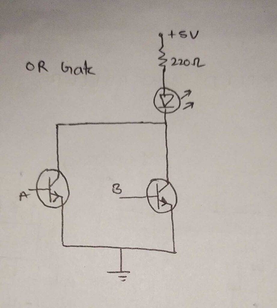
All connections are the same as AND gate except the following:
Connect the emitter pin of the first transistor with the emitter pin of the second transistor and join the collector pins of both the transistors with the negative rail.
We hope that now you are completely familiar with the working of logic gates and if you have any questions regarding the project you can ask them in the comments section below. Also, do check out more projects on Arduino and Raspberry Pi.
HAPPY LEARNING!