

Hi Tech Freaks, I’m back with another interesting and important tutorial based on Raspberry Pi. So, today we gonna see how we can connect Raspberry Pi with IR Sensor. IR sensor is a very common sensor to use and make projects, but it is not easy to use it with Raspberry Pi. So, to ease the problem for beginners, I’m here to help you. With this, we begin our journey on today’s topic.
IR Sensor:
- IR stands for Infra-Red. These sensors are basically a pair of IR transceivers LEDs. Which emit and receive IR light for detection of any object in front of them.
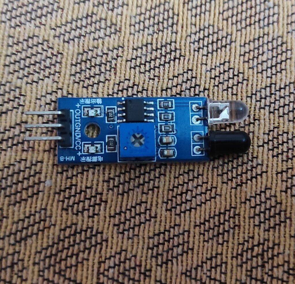
- The sensors are usually built out of LM358 op-amp which delivers 5V on OUT pin when something is in front of IR LEDs. But Nowadays, there is another model (whose image is given below) which is very much trending in the market.
- So, I’ll describe both. Also, code and explanation will be covered for both. This model is based on LM393.
- You can adjust the value of output by using potentiometers provided on the PCB of the module. Which will directly affect the range of the sensor until which it can detect any object.
- Also, since Raspberry Pi pins are only 3.3V Logic-Level tolerant, so it will be nice if you power the module with a 3.3V supply for safety purposes.
- It will not affect much for a short time, so for demonstration purposes I have used a 5V supply. But for long time usage, I highly ask you to use a 3.3V logic level to keep your Pi alive.
- The two different models which I have talked about of the IR sensor may differ only in the output ones give 5von output while GND on idle state while other GND on Output and 5V on idle state.
- For conversion of logic level voltage I recommend you to you a Logic level shifter instead of DIY version using Resistor
Material Required:
| Raspberry Pi with screen, keyboard & mouse | Raspberry Pi with screen, keyboard & mouse |
| IR sensor | BUY LINK |
| Buzzer | BUY LINK |
| RGB LED | BUY LINK |
| Jumper Wires | BUY LINK |
| Bread board | BUY LINK |
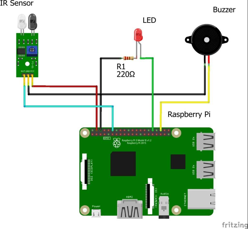
Circuit diagram:
Programming:
- So, first with these two statements we import Raspberry Pi GPIO module and sleep function from time module.
 import RPi.GPIO as gp
 from time import sleep
- Then we set pin referring to Board numbers. You can also set it to according to the BCM numbers, but learning them is a bit confusing, so I prefer Board numbers.
gp.setmode(gp.BOARD)
- After this, we define 3 pins as stated, 1 input for IR Sensor and 2 output for buzzer and LEDs
 gp.setup(12,gp.IN)
 gp.setup(32,gp.OUT)
 gp.setup(36,gp.OUT)
- For continuation of code, we write code in while loop. You can also write it inside the try & except to enable code termination at keyboard interrupt, but I have not included.
- For LM358 based sensors:
 print(gp.input(12))
 gp.output(32,gp.input(12))
 gp.output(36,gp.input(12))
- For LM393 based sensor:
 print(not gp.input(12))
 gp.output(32,not gp.input(12))
 gp.output(36,not gp.input(12))
- This ‘not’ invert the input of sensor received and hence give correct output for buzzer and LED
 import RPi.GPIO as gp
 from time import sleep
 gp.setmode(gp.BOARD)
 gp.setup(12,gp.IN)
 gp.setup(32,gp.OUT)
 gp.setup(36,gp.OUT)
 while True:
   print(not gp.input(12))
   gp.output(32,not gp.input(12))
   gp.output(36,not gp.input(12))
- You can change the Code with respect to your sensor type. If any problem arise then ask me down below, I’ll surely help you out. I hope you find this tutorial helpful.