
Hey techies, welcome back to Techatronic. In this article, we are going to learn how you can display the output voltage of a Solar panel on a 16×2 LCD using Arduino in this Arduino solar project. For this project, we are using an Arduino UNO microcontroller board. A 16×2 LCD is capable of displaying 16 alphanumeric characters in one row and it has a total of two rows. The I2C module that we use is just for reducing the connecting pins with Arduino. View more projects on Arduino.
How Does it Work?
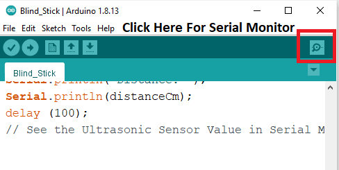
When the Solar panel is exposed to a light source it produces some output voltage which we can see on the 16×2 LCD. The Arduino read the output voltage produce by it and display the voltage on the LCD in volts. The LED connected with the Solar panel glows when voltage is produced. We are using an I2C module for interfacing with 16×2 LCD, it depends on you whether to use the I2C module or not in this Arduino solar project. We are provided you with both of the configurations. You can also check the output voltage values generated by the solar panel on the serial monitor. Use the image given below to locate the serial monitor. The final project looks like this. we have more solar projects like dual-axis solar trackers.

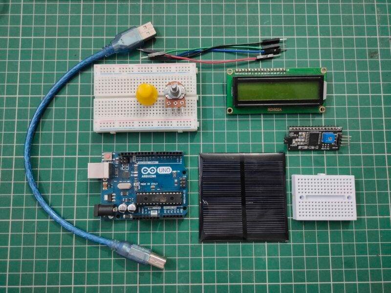
Components Required
| Arduino UNO | BUY LINK |
| Solar panel | BUY LINK |
| 16×2 LCD | BUY LINK |
| I2C module | BUY LINK |
| Jumper wires | BUY LINK |
| Breadboard | BUY LUNK |
| USB cable for uploading the code | BUY LINK |
| LED | BUY LINK |
| 220-ohm resistor | BUY LINK |
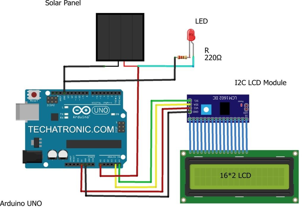
Circuit Diagram for the Project
- Using an I2C module
| Arduino UNO | I2C LCD Module | |
| A4 Pin | SDA Pin | |
| A5 Pin | SCL Pin | |
| ( +5V ) | VCC | |
| GND | GND | |
| 16 * 2 LCD | I2C LCD Module | |
| 16 Connect | 16 Connect | |
| Solar Panel | Led | 220-ohm Resistor |
| Positive | Terminal 1 | |
| Negative | Terminal 1 | |
| Terminal 2 | Terminal 2 |
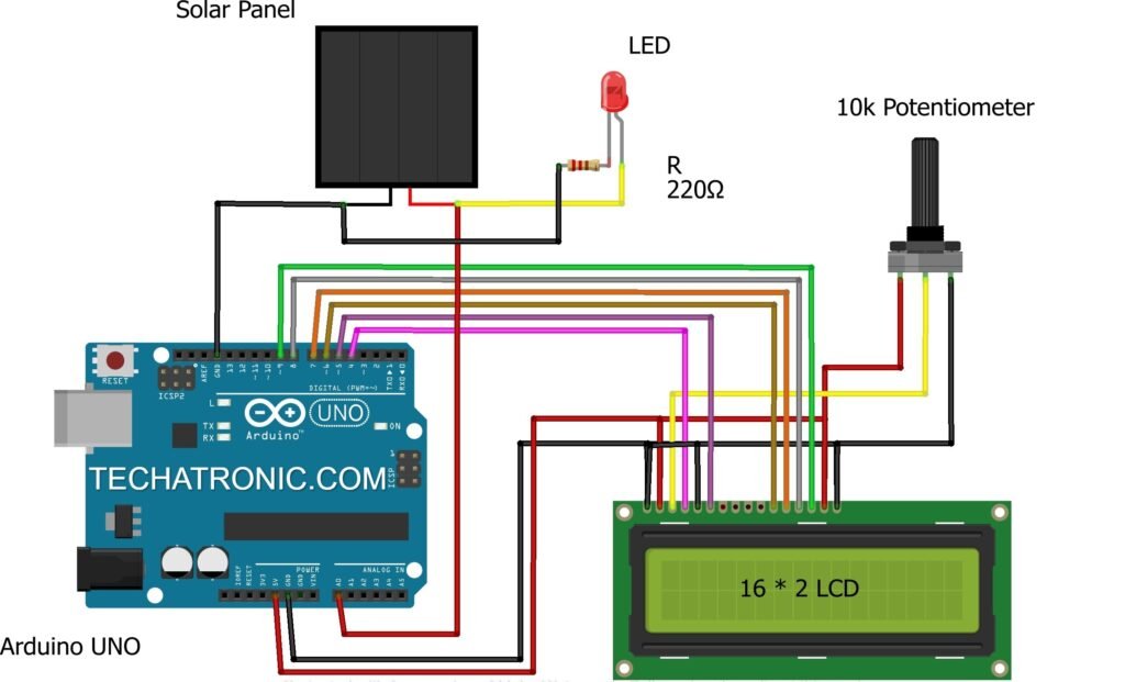
- Without using an I2C module
| Solar Panel | Led | 220-ohm Resistor |
| Positive | Terminal 1 | |
| Negative | Terminal 1 | |
| Terminal 2 | Terminal 2 | |
| Arduino UNO | 16*2 LCD | 10K Potentiometer |
| GND | VSS (Ground), K | Terminal 1 |
| +5V | VDD ( +5V ), A | Terminal 3 |
| VEE ( Contrast ) | Terminal 2 | |
| D12 Pin | RS ( Register Select ) | |
| GND | RW ( Read\Write ) | |
| D11 Pin | E ( Enable ) | |
| D5 Pin | D4 | |
| D4 Pin | D5 | |
| D3 Pin | D6 | |
| D2 Pin | D7 |
Circuit diagrams for both of the configurations are given. You can make any one of your choices. Connect the positive wire of the Solar panel with the analog-0 pin of the Arduino solar project and also with the positive wire of the LED. Join the negative wire of the Solar panel with the GND pin of the Arduino. Attach the negative wire of the LED with the GND pin of the Arduino through a 220-ohm resistor. If you are using an I2C module then connect the VCC and GND pins of the module with the 5-volts and GND pins of the Arduino. Attach the SCA and SCL pins of the module to the analog-4 and analog-5 pins of the Arduino. Use a breadboard for making common connections. Check the interfacing of an I2C module with a 16×2 LCD. If you are not using an I2C module then make the connections between Arduino digital pins and 16×2 LCD as shown in the diagram. You can check the interfacing of a 16×2 LCD with Arduino.
Code for the Project
Note: Please upload the given code to the Arduino. Make sure that you upload the code according to the circuit you have made. You need to install <LiquidCrystal.h>, <Wire.h>, <LiquidCrystal_I2C.h> libraries before uploading the code. Check how to add zip libraries to the Arduino IDE software.
- Using an I2C module
 // TECHATRONIC.COM
 // I2C LIBRARY
 //https://github.com/fdebrabander/Arduino-LiquidCrystal-I2C-library
 #include <Wire.h>
 #include <LiquidCrystal_I2C.h>
 LiquidCrystal_I2C lcd(0x27,16,2);
 void setup()
 {
  Serial.begin(9600); // sensor buart rate
  lcd.init();
  lcd.backlight();
 }
 void loop()
 {
  int sensorValue = analogRead(A0); // Solar Panel Positive PIN connect to A0
  float voltage = sensorValue * (5.0 / 1023.0);
   Serial.print("voltage  ");
   Serial.println(voltage);
   lcd.setCursor(0,0);
   lcd.print("VOLTAGE OF SOLAR");
   lcd.setCursor(0,1);
   lcd.print(voltage);
   lcd.setCursor(6,1);
   lcd.print("VOLT");
   delay(500);
 }
- Without using an I2C module
 // TECHATRONIC.COM
 #include "LiquidCrystal.h"
 LiquidCrystal lcd(9,8,7,6,5,4); // LCD Pin
 void setup()
 {
  Serial.begin(9600); // sensor buart rate
  lcd.begin(16,2);  // 16*2 LCD
 }
 void loop()
 {
  int sensorValue = analogRead(A0); // Solar Panel Positive PIN connect to A0
  float voltage = sensorValue * (5.0 / 1023.0);
   Serial.print("voltage  ");
   Serial.println(voltage);
   lcd.setCursor(0,0);
   lcd.print("VOLTAGE OF SOLAR");
   lcd.setCursor(0,1);
   lcd.print(voltage);
   lcd.setCursor(6,1);
   lcd.print("VOLT");
   delay(500);
 }
We hope that you learn this project well and must try to make it on your own. You can check some more tutorials on Arduino and Raspberry Pi made by us. If you are facing any problems do let us know in the comments section below.
HAPPY LEARNING!