
Table of Contents
Introduction
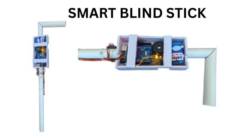
Hey techies, welcome back to Techatronic. In this article, we are going to make a Smart Blind Stick Using Arduino and Ultrasonic Sensor.
Smart blind stick is one of the trending project in the tech industry and robotics. so, we have made this project in very easy method. and upload all the instruction here with code and diagram. Also we have made the video too for this project.
Blind peoples have to face many challenges in their life, one of them is finding their way on the streets. On the streets, there are so many vehicles and obstacles that may block their way and also may injure them.
So keeping this problem in the mind we developed a Smart blind stick that scans for the obstacles in front of it with the help of an ultrasonic sensor. although we have share all the information of this project here. still if you have any problem to make this project we are also selling this ready made project and the link is given to buy the smart blind stick project.
You Can BUY SMART BLIND STICK from this link
For this project,
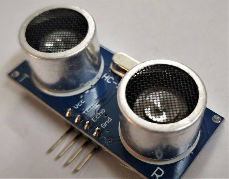
we use an HC-SR04 Ultrasonic sensor and Arduino UNO board. If you didn’t familiar with the working of the ultrasonic sensor with Arduino then please check it out first. Complete the circuit then upload the given code to the Arduino. You can present this project as your Arduino mini-project.
Working on the Smart Blind Stick
- The Smart Blind Stick scans the path in front of it with the help of an HC-SR04 Ultrasonic sensor.
- Whenever the sensor detects any object in its path the buzzer starts beeping and also at the same time the LED turns on.
- The blind person can hear the beeping of the buzzer and manage to change the way. In this way, the person can easily find his way without getting injured.
- This smart stick works in the same way as the Ultrasonic range finder did. You can also see the real-time values of the distance in cm on the Arduino serial monitor.
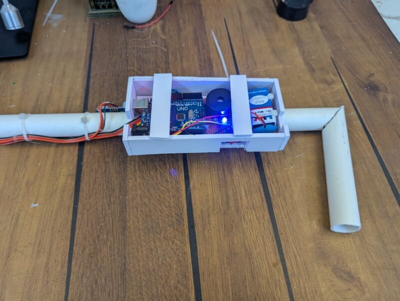
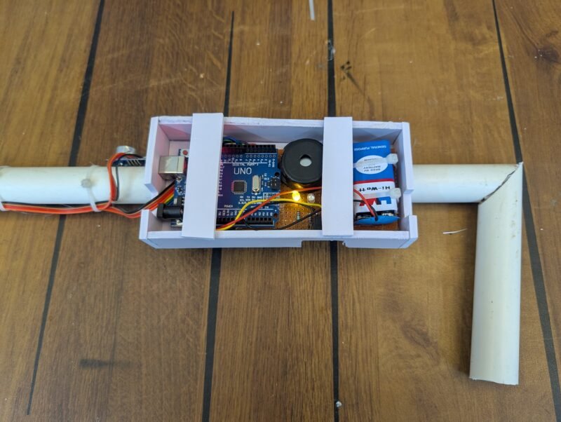
- Once the circuit is ready for this Arduino mini-project tie the whole set-up to a stick using zip ties.
Simulation
Components Required
- Arduino UNO –Buy Link
- USB cable for uploading the code –Buy Link
- Jumper wires –Buy Link
- Breadboard –Buy Link
- HC-SR04 ultrasonic sensor –Buy Link
- Buzzer –Buy Link
- LED with a 220-ohm resistor –Buy Link
- 9V DC batteries –Buy Link
Buy Smart blind stick Kit with user manual from our store
Circuit diagram for the Project
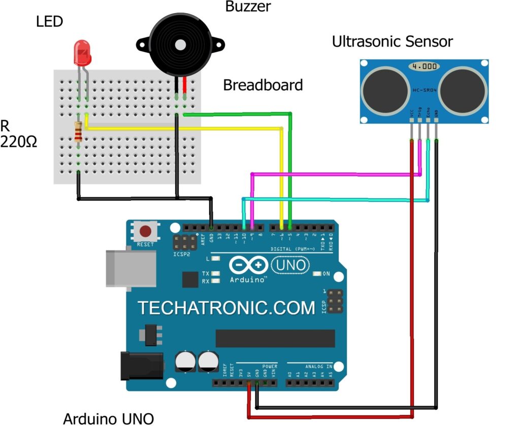
Connection Diagram
| Arduino UNO | Ultrasonic Sensor | |
| ( +5V ) | VCC | |
| GND | GND | |
| D9 Pin | Trig Pin | |
| D10 Pin | Echo Pin | |
| Arduino UNO | Buzzer | |
| D5 Pin | Positive Terminal | |
| GND | Negative Terminal | |
| Arduino UNO | LED | 220 Ohm Resistor |
| D6 Pin | Anode Pin | |
| Cathode Pin | Terminal 1 | |
| GND | Terminal 2 |
- Please make the connections according to the given Smart blind stick circuit diagram.
- Attach the 5-volts and GND pins of the Arduino to the VCC and GND pins of the ultrasonic sensor.
- Connect the TRIG and ECHO pins of the ultrasonic sensor with the digital-9 and digital-10 pins of the Arduino.
- Join the positive and negative wire of the buzzer with the digital-5 and GND pins of the Arduino.
- Attach the positive leg of the LED with the digital-6 pin of the Arduino and the negative leg of the LED with the GND pin of the Arduino through a 220-ohm resistor.
- You can use a breadboard for making common connections. Power the Arduino board using DC batteries.

Code for the Project
NOTE: You have to upload the given code to the Arduino.
// TECHATRONIC.COM

const int trigPin = 9;
const int echoPin = 10;
long duration;
int distanceCm, distanceInch;
void setup()
{

 Serial.begin(9600);
 pinMode(trigPin, OUTPUT);
 pinMode(echoPin, INPUT);

 pinMode(6, OUTPUT); // Connect LED Pin D6
 pinMode(5, OUTPUT); // Connect Buzzer Pin D5

}
void loop()
{
digitalWrite(trigPin, LOW);
delayMicroseconds(2);
digitalWrite(trigPin, HIGH);
delayMicroseconds(10);
digitalWrite(trigPin, LOW);
duration = pulseIn(echoPin, HIGH);
distanceCm= duration*0.034/2;
distanceInch = duration*0.0133/2;
Serial.println("Distance: ");
Serial.println(distanceCm);
delay (100);
// See the Ultrasonic Sensor Value in Serial Monitor


if(distanceCm < 25)  // You can Change the value
{

  digitalWrite(5, HIGH);  // Buzzer ON
  digitalWrite(6, HIGH);  // LED ON

}

else
{
    digitalWrite(5,LOW);  // Buzzer OFF
    digitalWrite(6,LOW);  // LED OFF
}
}
Now you open the serial monitor to read the sensor value


Working:-
As, you know the working of this project is very simple. there is an ultrasonic sensor which is continously measuring the distance from any object or person. and we have made condition according to the ultrasonic sensor output. such as we took the distance 25 as threshold. it means if the distance between the sensor and the object is less than 25 then the arduino give instructions to the the buzzer to make noise.
Video sample
Related project
Smart Ultrasonic Distance Finder Using 3 Ultrasonic Sensors
Blynk Ultrasonic sensor | HC-SR04
What is ultrasonic sensor with Arduino? Tutorial of Ultrasonic Sensor
Radar using Arduino & Ultrasonic sensor
raspberry pi pico ultrasonic sensor | Raspberry pi Pico Tutorial
ultrasonic sensor with raspberry pi
We hope that you understand the project well and try to make it on your own. If you are facing any difficulties do inform us in the comments section below. Please check more Tutorials on Arduino and Raspberry Pi.