
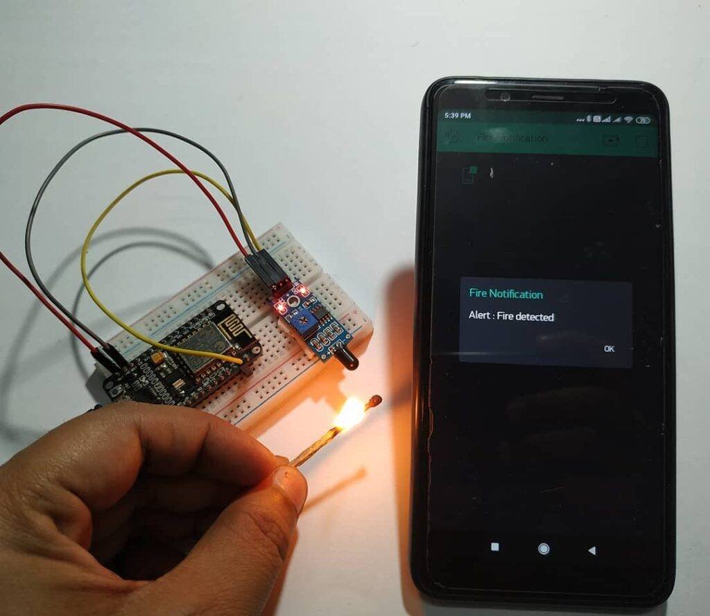
Hey Tech Folks, Today we are going to make a very useful DIY thing that is needed for every house. Blynk Fire Alarm, yes you have guessed it right. It is a fire alarm that runs on a small microcontroller like NodeMCU & flame sensor. We’ll configure this with Blynk App for IoT notification on various devices. Also, you can do more stuff with this by adding various other tasks via Blynk App. You may also visit its Arduino Tutorial for more practical implementation knowledge. So, let’s begin.
Flame Sensor:
Like other sensors, this sensor is also very common among tech hobbyists and project makers. This sensor is based on the principle of detection of Infrared Light. This sensor is very simple and built out of LM393 IC. It is a Comparator IC that is used as Op-Amp in this sensor. As stated before, this sensor works on the principle of detection of infrared light. But if you wonder how, then just read further to get an idea of it.
Whenever there is fire there is the emission of Infrared spectrum which can be detected by any infrared cameras and detectors. But these seem to be very costly, to lesser the cost we use IR receiver led or photodiode to receive the infrared spectrum emitted by fire. The photodiode is not very effective as other imaging devices. But it can be used for this purpose.
The sensor has a potentiometer that can be used to trim the values which are being sent to the microcontroller. It can give both types of outputs, i.e., Analog and Digital. But take this in mind, although photodiode is effective for this job. But it is vulnerable to sunlight, as sunlight also consists of the infrared spectrum which can be detected by a photodiode and can result in malfunctioning of the sensor and wrong values.
Material Required:
- NodeMCU (ESP8266 MOD)
- Flame sensor
- Jumper wires
- Breadboard
- Phone with Wi-Fi connection
Circuit Design:

| Nodemcu esp8266 | Flame Sensor |
| D1 Pin | DO Pin |
| ( +5V ) VCC | + ( Positive ) |
| GND | G ( Negative ) |
Code & Explanation:
Explanation:
Firstly, we import some important libraries for the function of code. Along with this, we create some objects like BLYNK_PRINT & timer which are required further in code. Also, we create some variables to store our Wi-Fi credentials.
Then we create a custom function named notify fire() which checks for a condition button pressed and flag and on that basis, it checks the flame sensor for analog output. Along with this, it updates the text on Blynk App to ‘Alert: Fire detected’.
 void notifyOnFire()
 {
  int isButtonPressed = digitalRead(D1);
  if (isButtonPressed==1 && flag==0) {
   Serial.println("Fire DETECTED");
   Blynk.notify("Alert : Fire detected");
   flag=1;
  }
  else if (isButtonPressed==0)
  {
   flag=0;
  }
 }
Then in the setup section, we define pinMode and start communication with Blynk App. In the loop section, we simply run the time interval and notifiyOnfire function for getting output.
 void setup()
 {
 Serial.begin(9600);
 Blynk.begin(auth, ssid, pass);
 pinMode(D1,INPUT_PULLUP);
 timer.setInterval(1000L,notifyOnFire);
 }
 void loop()
 {
  Blynk.run();
  timer.run();
 }
Code:
Here is the main code
 //TECHATRONIC.COM
 // BLYNK LIBRARY
 // https://github.com/blynkkk/blynk-library
 // ESP8266 LIBRARY
 // https://github.com/ekstrand/ESP8266wifi
 #define BLYNK_PRINT Serial
 #include <ESP8266WiFi.h>
 #include <BlynkSimpleEsp8266.h>
 BlynkTimer timer;
 char auth[] = "your-auth-code"; //Auth code sent via Email
 char ssid[] = "your-wifi-ssid"; //Wifi name
 char pass[] = "your-wifi-password"; //Wifi Password
 int flag=0;
 void notifyOnFire()
 {
  int isButtonPressed = digitalRead(D1);
  if (isButtonPressed==1 && flag==0) {
   Serial.println("Fire DETECTED");
   Blynk.notify("Alert : Fire detected");
   flag=1;
  }
  else if (isButtonPressed==0)
  {
   flag=0;
  }
 }
 void setup()
 {
 Serial.begin(9600);
 Blynk.begin(auth, ssid, pass);
 pinMode(D1,INPUT_PULLUP);
 timer.setInterval(1000L,notifyOnFire);
 }
 void loop()
 {
  Blynk.run();
  timer.run();
 }
Blynk Connection:
Download and install the Blynk app from your preferred app store. Also, login into the app using your social account.
Remember that the account used for login will be used to send auth-token, which is used in code in Arduino.

Now create a new project with the desired name. Here I have used ‘Fire notification’.
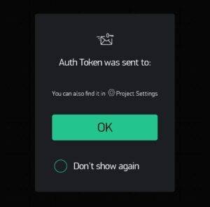
auth-token will be sent to your registered email as soon as you create a new project.

Now you will be headed over to the main page where you can add widgets from the widgets tray.
##insertpichere##
Drag and drop selected widget’s tray as same in the above picture.

Now the main screen will look like this and with this you are ready to go.
Now connect the power source to NodeMCU and wait on the serial monitor to display something like this.

This confirms that your project Blynk Fire Alarm is completed, and you are all set to see it working.
Now as we have completed this tutorial successfully, it’s time to say goodbye. Until then reply to me in a comment if you face any issues, I hope you enjoy this post also.