
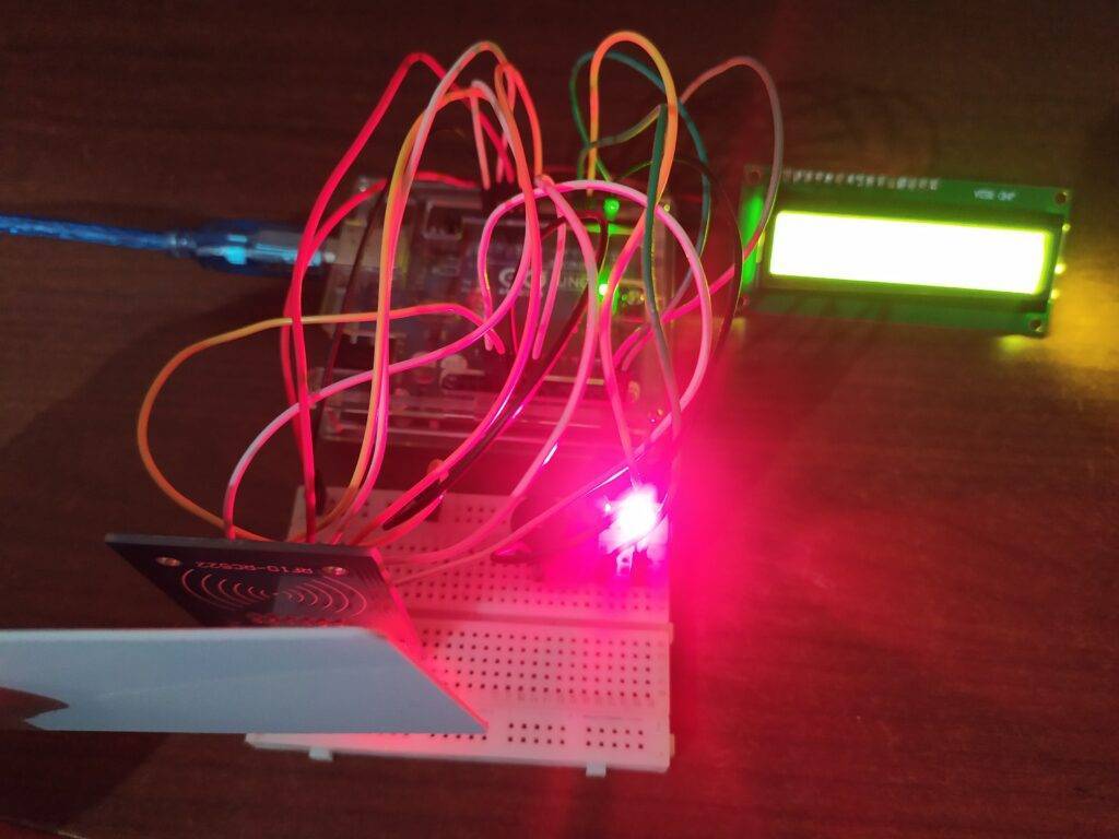
Hello geeks, hope you are doing fine. On our school or college days, we have to answer our roll calls, and then the teacher marks us present. Have you ever wonder that what if we have a smart card to mark our attendance? So keeping this in mind we are writing this article to make an RFID-based attendance system using Arduino UNO board. The students can enroll themself by just placing the smart card on the reader module. For doing this we are using an RC522 RFID reader and writer module. Do check out more projects on Arduino.

How Does RFID-based attendance system Work?
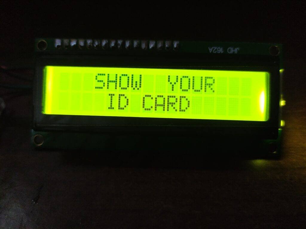
This system works on radio frequency identification. The smart card which you have to put on the reader module is pre-coded with the roll number. Whenever someone uses a card whose information is not registered in the memory the red LED will go on and the buzzer starts beeping. When the system is on it will ask you to show your smart card. For displaying the contents we are using a 16×2 LCD with an I2C module.
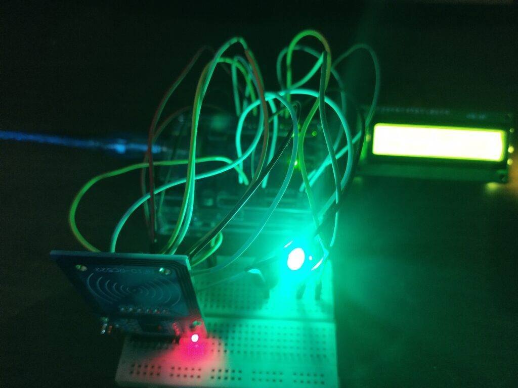
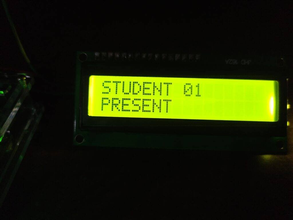
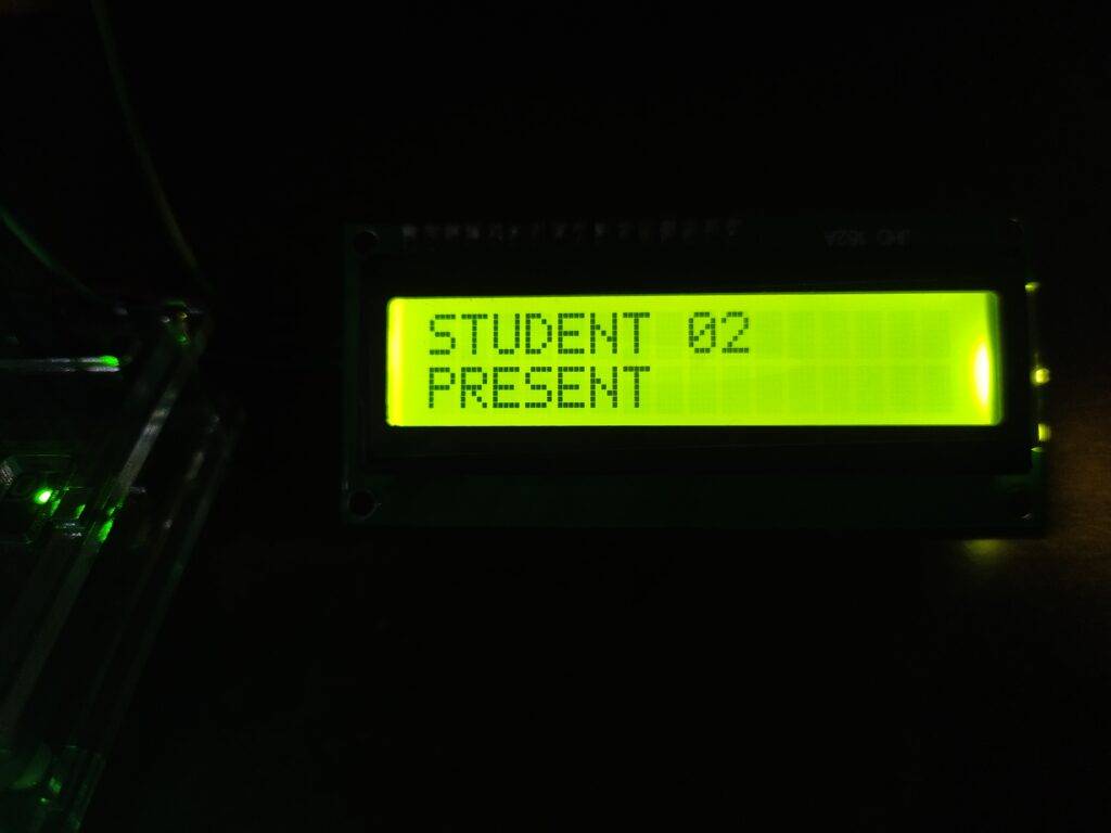
When the RFID reads the card that is coded with the correct details the Green LED will glow. The LCD will display the name of the student and a message “present“.
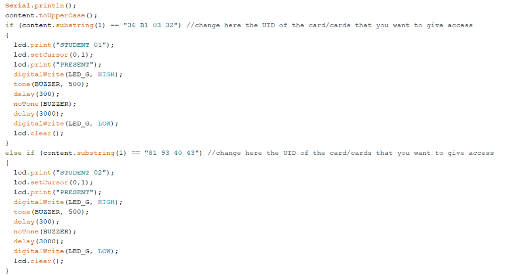
You can add as many students as you want and also change their names by modifying the code.
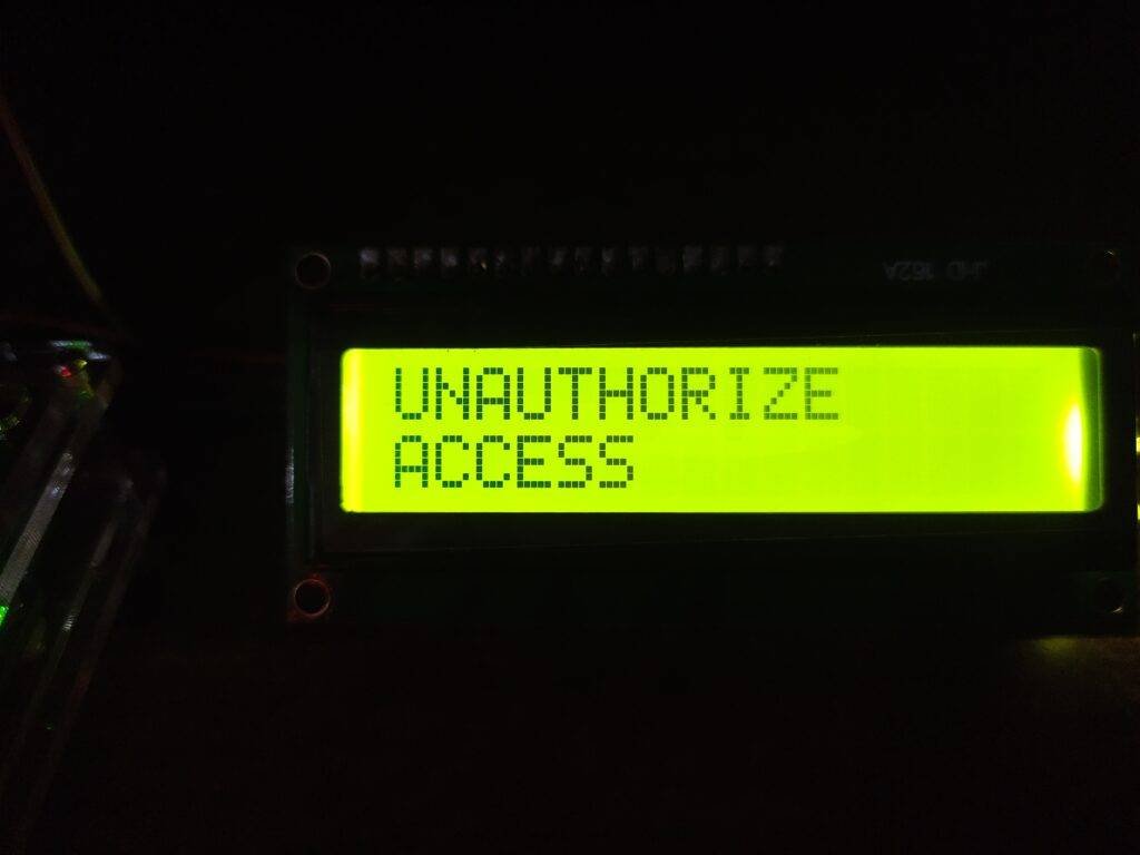
If the details of the card are not present then the Red LED will be on and the LCD displays “unauthorized access” as shown below.
We are giving the circuit diagrams for both, with and without the I2C module, and please make sure that you upload the code according to the circuit you have made.
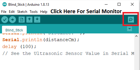
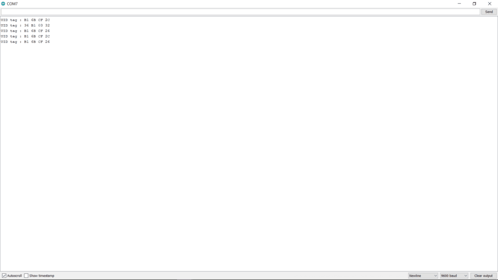
Add your card by using the tag id which you can find in the serial monitor as shown below.
Components Required
| Arduino UNO | BUY LINK |
| RC522 RFID module | BUY LINK |
| Jumper wires | BUY LINK |
| Red and green LED | BUY LINK |
| 220-ohm resistor | BUY LINK |
| I2C module | BUY LINK |
| 16×2 LCD display | BUY LINK |
| USB cable for uploading the code | BUY LINK |
| Buzzer | BUY LINK |
| breadboard | BUY LINK |
rfid based attendance system Circuit Diagram
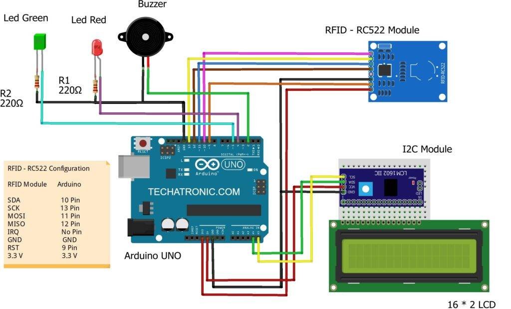
Before starting check the address of your I2C module.
Arduino 5-volts pin -> VCC of the I2c module
Arduino GND pin -> GND of the I2C module
Arduino analog-4 pin -> SDA of the I2C module
Arduino analog-5 pin -> SCL of the I2C module
Arduino digital-2 pin -> positive leg of buzzer
Arduino digital-4 pin -> positive leg of red LED
Arduino digital-5 pin -> positive leg of green LED
You can also check how to use an I2C module with LCD.
Without I2C module

All the connections are the same, connect the LCD pins with the Arduino pins as shown above. Please read the interfacing of LCD with Arduino if you don’t understand the connections.
rfid based attendance system Code
NOTE: Please install <SPI.h>, <MFRC522.h>, <Wire.h>, <LiquidCrystal_I2C.h> libraries to the IDE first and then upload the code which is given below. If you don’t know how to add a zip library in the IDE software then go through it once.
With I2C module
 // Techatronic.com
 #include <SPI.h>
 #include <MFRC522.h>
 #include <Wire.h>
 #include <LiquidCrystal_I2C.h>
 // Set the LCD address to 0x27 for a 16 chars and 2 line display
 LiquidCrystal_I2C lcd(0x27, 16, 2);
 #define SS_PIN 10
 #define RST_PIN 9
 #define LED_G 5 //define green LED pin
 #define LED_R 4 //define red LED pin
 #define BUZZER 2 //buzzer pin
 MFRC522 mfrc522(SS_PIN, RST_PIN);  // Create MFRC522 instance.
 void setup()
 {
  Serial.begin(9600);  // Initiate a serial communication
  SPI.begin();   // Initiate SPI bus
  mfrc522.PCD_Init();  // Initiate MFRC522
  lcd.begin();
  lcd.backlight(); // Turn on the blacklight and print a message.
  pinMode(LED_G, OUTPUT);
  pinMode(LED_R, OUTPUT);
  pinMode(BUZZER, OUTPUT);
  noTone(BUZZER);
 }
 void loop()
 {
  // Look for new cards
  if ( ! mfrc522.PICC_IsNewCardPresent())
  {
  lcd.setCursor(3,0);
  lcd.print("SHOW YOUR");
  lcd.setCursor(4,1);
  lcd.print("ID CARD");
  return;
  }
  else{
    lcd.clear();
  }
  // Select one of the cards
  if ( ! mfrc522.PICC_ReadCardSerial())
  {
   return;
  }
  //Show UID on serial monitor
  Serial.print("UID tag :");
  String content= "";
  byte letter;
  for (byte i = 0; i < mfrc522.uid.size; i++)
  {
    Serial.print(mfrc522.uid.uidByte[i] < 0x10 ? " 0" : " ");
    Serial.print(mfrc522.uid.uidByte[i], HEX);
    content.concat(String(mfrc522.uid.uidByte[i] < 0x10 ? " 0" : " "));
    content.concat(String(mfrc522.uid.uidByte[i], HEX));
  }
  Serial.println();
  content.toUpperCase();
  if (content.substring(1) == "36 B1 03 32") //change here the UID of the card/cards that you want to give access
  {
   lcd.print("STUDENT 01");
   lcd.setCursor(0,1);
   lcd.print("PRESENT");
   digitalWrite(LED_G, HIGH);
   tone(BUZZER, 500);
   delay(300);
   noTone(BUZZER);
   delay(3000);
   digitalWrite(LED_G, LOW);
   lcd.clear();
  }
  else if (content.substring(1) == "81 93 40 43") //change here the UID of the card/cards that you want to give access
  {
   lcd.print("STUDENT 02");
   lcd.setCursor(0,1);
   lcd.print("PRESENT");
   digitalWrite(LED_G, HIGH);
   tone(BUZZER, 500);
   delay(300);
   noTone(BUZZER);
   delay(3000);
   digitalWrite(LED_G, LOW);
   lcd.clear();
  }
  else if (content.substring(1) == "91 69 3E 43") //change here the UID of the card/cards that you want to give access
  {
   lcd.print("STUDENT 03");
   lcd.setCursor(0,1);
   lcd.print("PRESENT");
   digitalWrite(LED_G, HIGH);
   tone(BUZZER, 500);
   delay(300);
   noTone(BUZZER);
   delay(3000);
   digitalWrite(LED_G, LOW);
   lcd.clear();
  }
  else  {
   lcd.print("UNAUTHORIZE");
   lcd.setCursor(0,1);
   lcd.print("ACCESS");
   digitalWrite(LED_R, HIGH);
   tone(BUZZER, 300);
   delay(2000);
   digitalWrite(LED_R, LOW);
   noTone(BUZZER);
   lcd.clear();
  }
 }
Without I2C module
 #include <SPI.h>
 #include <MFRC522.h>
 #include "LiquidCrystal.h"
 LiquidCrystal lcd(A0, A1, A2, A3, A4, A5);
 #define SS_PIN 10
 #define RST_PIN 9
 #define LED_G 5 //define green LED pin
 #define LED_R 4 //define red LED pin
 #define BUZZER 2 //buzzer pin
 MFRC522 mfrc522(SS_PIN, RST_PIN);  // Create MFRC522 instance.
 void setup()
 {
  Serial.begin(9600);  // Initiate a serial communication
  SPI.begin();   // Initiate SPI bus
  mfrc522.PCD_Init();  // Initiate MFRC522
  lcd.begin(16,2); // Turn on the blacklight and print a message.
  pinMode(LED_G, OUTPUT);
  pinMode(LED_R, OUTPUT);
  pinMode(BUZZER, OUTPUT);
  noTone(BUZZER);
 }
 void loop()
 {
  // Look for new cards
  if ( ! mfrc522.PICC_IsNewCardPresent())
  {
  lcd.setCursor(3,0);
  lcd.print("SHOW YOUR");
  lcd.setCursor(4,1);
  lcd.print("ID CARD");
  return;
  }
  else{
    lcd.clear();
  }
  // Select one of the cards
  if ( ! mfrc522.PICC_ReadCardSerial())
  {
   return;
  }
  //Show UID on serial monitor
  Serial.print("UID tag :");
  String content= "";
  byte letter;
  for (byte i = 0; i < mfrc522.uid.size; i++)
  {
    Serial.print(mfrc522.uid.uidByte[i] < 0x10 ? " 0" : " ");
    Serial.print(mfrc522.uid.uidByte[i], HEX);
    content.concat(String(mfrc522.uid.uidByte[i] < 0x10 ? " 0" : " "));
    content.concat(String(mfrc522.uid.uidByte[i], HEX));
  }
  Serial.println();
  content.toUpperCase();
  if (content.substring(1) == "36 B1 03 32") //change here the UID of the card/cards that you want to give access
  {
   lcd.print("STUDENT 01");
   lcd.setCursor(0,1);
   lcd.print("PRESENT");
   digitalWrite(LED_G, HIGH);
   tone(BUZZER, 500);
   delay(300);
   noTone(BUZZER);
   delay(3000);
   digitalWrite(LED_G, LOW);
   lcd.clear();
  }
  else if (content.substring(1) == "81 93 40 43") //change here the UID of the card/cards that you want to give access
  {
   lcd.print("STUDENT 02");
   lcd.setCursor(0,1);
   lcd.print("PRESENT");
   digitalWrite(LED_G, HIGH);
   tone(BUZZER, 500);
   delay(300);
   noTone(BUZZER);
   delay(3000);
   digitalWrite(LED_G, LOW);
   lcd.clear();
  }
  else if (content.substring(1) == "91 69 3E 43") //change here the UID of the card/cards that you want to give access
  {
   lcd.print("STUDENT 03");
   lcd.setCursor(0,1);
   lcd.print("PRESENT");
   digitalWrite(LED_G, HIGH);
   tone(BUZZER, 500);
   delay(300);
   noTone(BUZZER);
   delay(3000);
   digitalWrite(LED_G, LOW);
   lcd.clear();
  }
  else  {
   lcd.print("UNAUTHORIZE");
   lcd.setCursor(0,1);
   lcd.print("ACCESS");
   digitalWrite(LED_R, HIGH);
   tone(BUZZER, 300);
   delay(2000);
   digitalWrite(LED_R, LOW);
   noTone(BUZZER);
   lcd.clear();
  }
 }
We hope that you understand the concept of the project and must try to make it on your own. For any suggestions or quarries please feel free to use the comments section given below. Also, do check out tutorials on Arduino and Raspberry Pi.
HAPPY LEARNING!
We are working on project on RFID attendance system so we have the components like Breadboard 16×2 LCD monitor I2C Interface adapter Arduino UNO Tiny DS1307 RTC module RFID sensor jumper wires buzzer led lights red and green can u please us with the connections as we are unable to execute it we say a video in youtube and made connections using these components but at the end when we were set RTC code for real time clock we are frequently getting RTC error and after finding resulted like there is mistake circuit connection so please help us with connection and code so that we can present our model for our college project we saw your project description but we also want to use RTC module to display time so please help us with connection code to upload
ALL GROUND (GND) MUST BE COMMON
Arduino GND → RFID GND → RTC GND → LCD GND → Buzzer GND,
Never connect RC522 to 5V
If SDA/SCL are reversed → RTC error
VCC 5V
GND GND
SDA A4
SCL A5
SDA/SCL swapped
❌ No common ground
❌ Weak or dead CR2032 battery
❌ Using DS3231 code for DS1307
❌ I2C address mismatch
#include
#include
RTC_DS1307 rtc;
void setup() {
Serial.begin(9600);
if (!rtc.begin()) {
Serial.println(“RTC NOT FOUND”);
while (1);
}
if (!rtc.isrunning()) {
Serial.println(“RTC NOT RUNNING, SETTING TIME”);
rtc.adjust(DateTime(F(__DATE__), F(__TIME__)));
}
}
void loop() {
DateTime now = rtc.now();
Serial.print(now.day());
Serial.print(“/”);
Serial.print(now.month());
Serial.print(“/”);
Serial.print(now.year());
Serial.print(” “);
Serial.print(now.hour());
Serial.print(“:”);
Serial.print(now.minute());
Serial.print(“:”);
Serial.println(now.second());
delay(1000);
}