

Table of Contents
Introduction
Hello guys, hope you are doing fine. I am back with another new tutorial on nodemcu. In this article, we are going to learn how an IR sensor works with an esp8266 nodemcu board.

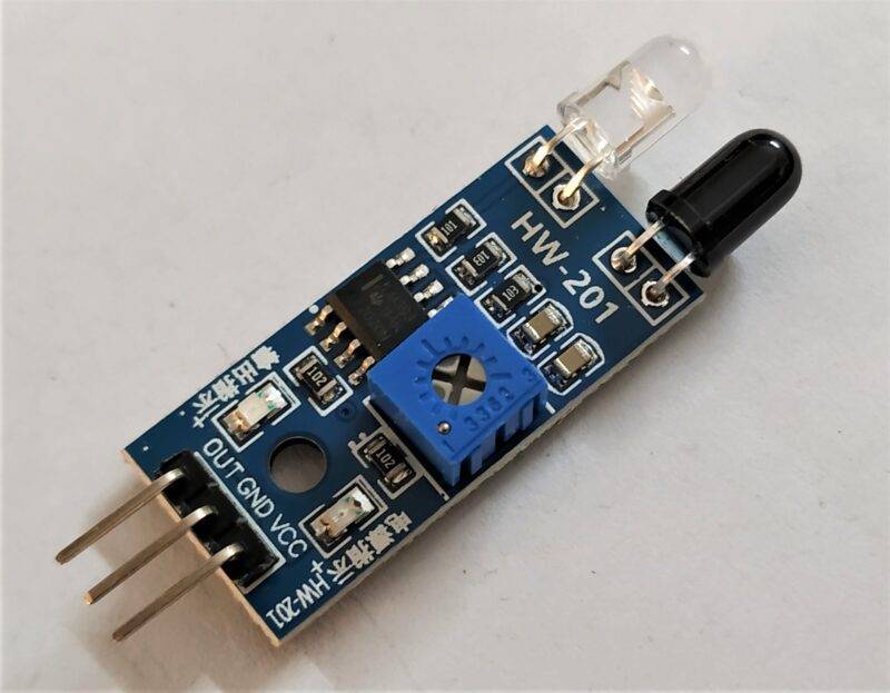
Before starting, I want to give some details about the IR sensor, so basically it is an infrared sensor that uses infrared radiations to detect some object.
in this nodemcu tutorial. According to science, every object emits some heat. This sensor is consists of one emitter and one receiver LED.
You can’t see the radiations of light emitted by the IR sensor with the naked eyes but you can see it by using a camera. All the important materials like circuit diagrams and code are also given below for your convenience.
You can also read our articles on Arduino and IoT. So without wasting more time let’s check out the working of the project.
Working of the Project
There are two ways in which we can use an IR sensor with the nodemcu tutorial that are analog connections and digital connection.
- Set the baud rate to 9600 for serial communication with the system.
- Define the pin at which you connect the LED.
- Initially, the LED will turn on. In the loop section,
- we are continuously reading the output which is generated by the IR sensor and printing the values on the serial monitor screen.

You can find the serial monitor at the top-most right corner of the Arduino IDE software and how to set nodemcu in Arduino IDE.
If the values are less than 900 then the LED will glow. You can change this value as per your need. Also, check out how an IR sensor works with the Arduino UNO board.
Also check the major project And IOT project
Software simulation digital output

Software simulation analog output

Components Required
| ESP8266 nodemcu | BUY LINK |
| IR Sensor | BUY LINK |
| LED | BUY LINK |
| 220-ohm resistor | BUY LINK |
| Jumper wires | BUY LINK |
| breadboard | BUY LINK |
| USB cable for uploading the code | BUY LINK |
Circuit Diagram for the Project
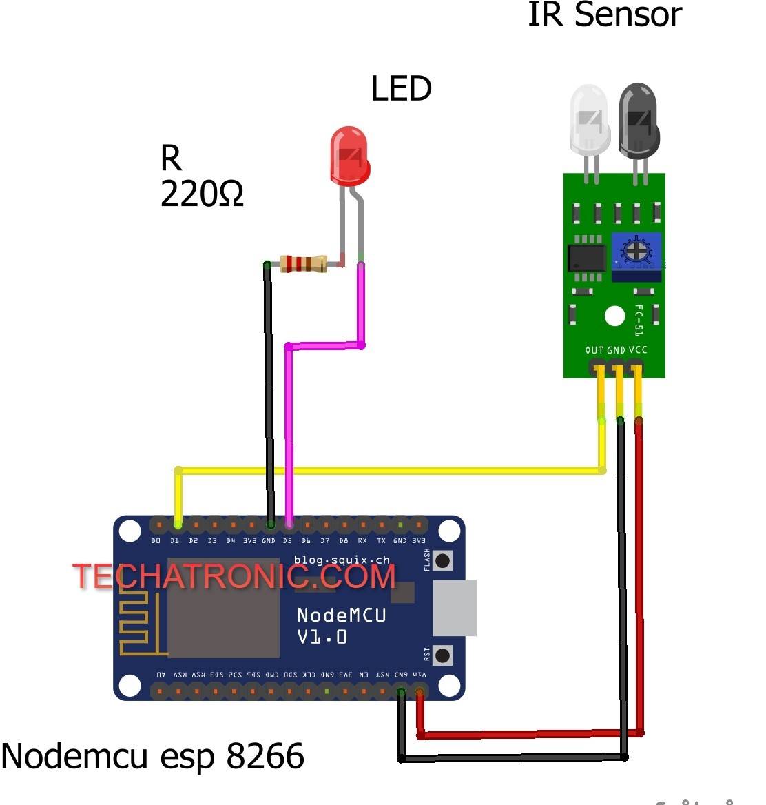
Connection Table
| Nodemcu esp8266 | IR sensor | |
| Vin | VCC | |
| G | GND | |
| D1 Pin | OUT Pin | |
| Nodemcu | LED | 220 Ohm Resistor |
| D5 Pin | Anode | |
| Cathode | Terminal 1 | |
| GND | Terminal 2 |

Take the IR sensor and place it on a breadboard so that the sensor can standstill. Now connect three jumper wires to it. Connect the VCC pin of the IR sensor with the VIN pin of the nodemcu. Join the GND pin of the IR sensor with the GND pin of the nodemcu. Connect the OUT pin of the sensor with the digital-1 pin of the nodemcu. Take an LED and connect its positive leg with the digital-5 pin. Join the negative leg of the LED with the GND pin of the nodemcu via a 220-ohm resistor. Now your connections are complete and you can proceed to the code section.also learn the nodemcu iot project
for analog connection
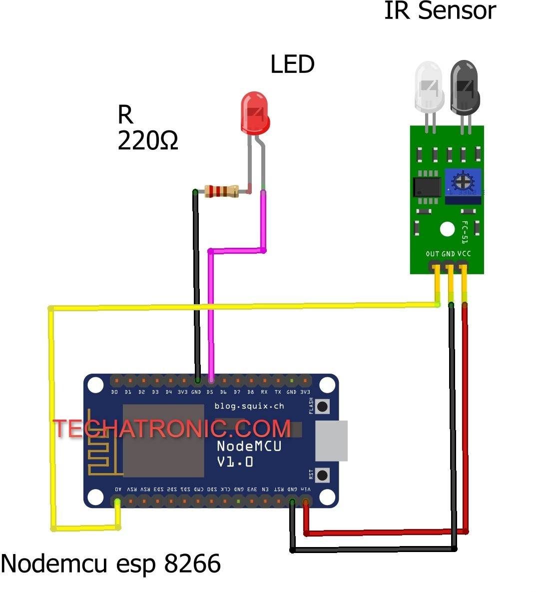
Connection Table
| Nodemcu esp8266 | IR sensor | |
| Vin | VCC | |
| G | GND | |
| A0 Pin | OUT Pin | |
| Nodemcu | LED | 220 Ohm Resistor |
| D5 Pin | Anode | |
| Cathode | Terminal 1 | |
| GND | Terminal 2 |
Just repeat the same connections that you have done above but in this connect the OUT pin of the IR sensor with the analog-0 pin of the nodemcu tutorial.
Code for the Project
NOTE: Please upload the code which is given below to the nodemcu as it is.
digital connection code
 // TECHATRONIC.COM
 int val = 0 ;
 void setup()
 {
   Serial.begin(9600); // sensor buart rate
   pinMode(14,HIGH);  // Led Pin Connected To D5 Pin
 }
 void loop()
 {
  val = digitalRead(5); // IR Sensor output pin connected to D1
  Serial.println(val);  // see the value in serial m0nitor in Arduino IDE
  delay(100);      // for timer
  if(val == 1 )
  {
   digitalWrite(14,HIGH); // LED ON
  }
  else
  {
   digitalWrite(14,LOW); // LED OFF
  }
  }
analog connection code
 // TECHATRONIC.COM
 void setup()
 {
   Serial.begin(9600); // sensor buart rate
   pinMode(14,HIGH);  // Led Pin Connected To D5 Pin
 }
 void loop()
 {
  int s1=analogRead(A0); // IR Sensor output pin connected to A0
  Serial.println(s1);  // See the Value In Serial Monitor
  delay(100);
  if(s1< 900 )
  {
   digitalWrite(14,HIGH); // LED ON
  }
   else
  {
   digitalWrite(14,LOW); // LED OFF
  }
 }

IoT Projects for final year – IR sensor Notification IoT
How to setup NodeMCU Arduino IDE
Obstacle Detector By IR Sensor with Arduino
Smart Dustbin With Arduino and IR Sensor
We hope that you like this tutorial and understand all the concepts that we are trying to explain in this article. If you have any doubts regarding this project then please ask them in the comments section below. Also, do check out more such tutorials on Arduino and Raspberry Pi.
video sample
HAPPY LEARNING!