
Hello there. Welcome to our website. Are you working on Flex Sensor-based project? Do you want to know how the sensor works? Do you want to make a hand movement-controlled robotic device? Well, In this article we will be discussing how to interface the sensor with Arduino in a detailed Step-by-step guide and we will also see the circuit diagram, components required, and Arduino code. I hope you will like the article. We have already made various Arduino projects, Embedded projects, and Arduino tutorials on our website. You can visit them if you are new to the world of electronics and Arduino. you will find them helpful.

What is Flex Sensor?
This is a sensor that measures the change in the direction of the sensor with respect to its normal position. When there is any bend or change in its shape, it gives a change in its readings. This data is Analog type in the range of 0-1023. so there we can use this sensor to make multiple conditions. that we used in our sign language project which is the biggest hit over the internet.
Nowadays, many people are working on projects such as hand-controlled or movement-controlled robots, which use the same type of flex sensors to transfer the physical hand movement into an electrical signal. One can also make their own hand movement-controlled toys using five different sensors for five different fingers as their fun DIY project.
How does It Work?
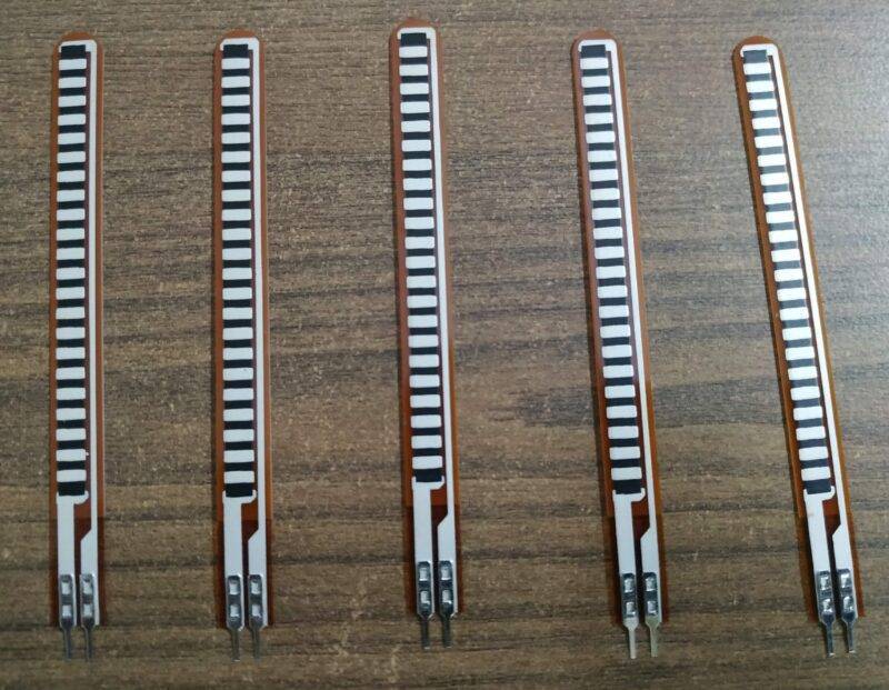
This works on the basis of variable resistance such as a potentiometer. The resistance of the sensor changes with the angle to which it is bent. there as many types of flex sensors available in the market but the one we are using here is the resistive type. it is thin and long about 10 cm. the flex sensor may use in robotics. many people use this flex sensor in the animatronic hand. this can be the best final year project for ECE students.
Inside the sensor, there are conductive strips placed on top of each other. when there is bent, they make contact at different points, thereby increasing the resistance. the resistance values of each individual sensor may have some difference, hence one must understand this before using them in their project.
Components Required
| Arduino UNO | BUY LINK |
| Flex sensor | BUY LINK |
| Jumper Wires | BUY LINK |
| Breadboard | BUY LINK |
| 10K ohm Resistor | BUY LINK |
| 2x 220 ohm resistor | BUY LINK |
| LED’s (Blue and Green) | BUY LINK |
| USB Cable for uploading the code | BUY LINK |

Flex Sensor Working With Arduino Circuit Diagram
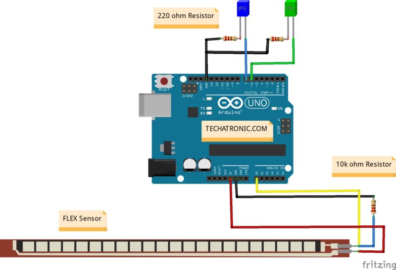
| Arduino | Flex Sensor | 10k ohm Resistor | |
| ( +5V ) | Terminal 1 | ||
| A0 Pin | Terminal 2 | Terminal 1 | |
| GND | Terminal 2 | ||
| Arduino UNO | LED B | LED B | 220 Ohm Resistor |
| D7 Pin | Anode Pin | ||
| D6 Pin | Anode Pin | ||
| GND | Terminal 1 | ||
| Cathode Pin | Cathode Pin | Terminal 2 |
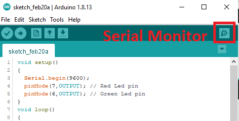
Serial Monitor

// Techatronic.com Flex Sensor Working With Arduino Code
 void setup()
 {
   Serial.begin(9600);
   pinMode(7,OUTPUT); // Red Led pin
   pinMode(6,OUTPUT); // Green Led pin
 }
 void loop()
 {
  int s1=analogRead(A0);
  Serial.println(s1);
  delay(50);
  if(s1>100 )
  {
   digitalWrite(7,LOW);  // Red Led off
   digitalWrite(6,HIGH); // Green Led on
  }
   else
  {
   digitalWrite(7,HIGH); // Red Led on
   digitalWrite(6,LOW); // Green Led off
  }
 }
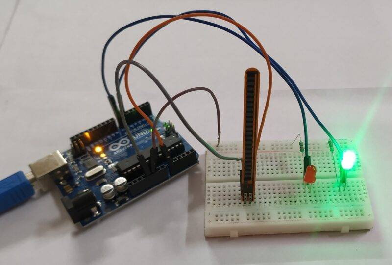
Once the above Arduino code uploading is done, you can test the working of it by bending the sensor and looking at the color of the led. If the color is Green when bent, it is working. I hope you found this tutorial helpful. If you have any queries or doubts, you can ask them in the comment section below.