

Welcome to Techatronic, in this article we are going to discuss automatic railway gate control using Arduino and IR sensor modules.
If you have an interest in Arduino and related projects do check out here for more. Arduino is a microcontroller that uses ATmega328p IC for its functioning.
There are many types of Arduino boards available but in this project, we use Arduino UNO. IR sensor module, also known as Proximity Sensors, has three pins, two of them are for power, and one is for the output signal. Please check more projects on IR sensors here.
Learn how to make automatic railway gate control by just following the easy procedure discussed below.
How Does it Work?
The “Automatic Railway Gate Control” is basically a smart automatic barrier that allows the traffic to cross the railway track when there is no train and blocks the traffic when a train passes through tracks. This is how the automatic railway gate control works
Make the connections according to the circuit diagram and upload the Arduino code both are provided in this article. Set up the toy train and join the tracks and their accessories.
Place one of the IR sensors on either side of the track and the other in its opposite direction so that both can easily detect the movement of the train at different positions. Place the servo with a barrier attached to it so it can move up and down easily.
Provide the power supply to the Arduino so that the project starts working. When the train arrives the first IR sensor detects it and the servo barrier blocks the crossing when the second sensor detects that the train goes away the servo barrier opens. In this way, the system works.
Components Required
- Arduino UNO
- Servo motor
- Two IR Sensor Modules
- Toy Train
- DC Adapter to Power the Arduino
- Jumper Wires
- USB cable for uploading code into Arduino UNO
- Breadboard
Circuit Diagram of the Project
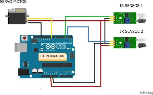
Make connections according to the above diagram. Connect Arduino’s 5V pin with the VCC pin of both the IR sensors and the positive wire of the servo motor. Connect the Arduino’s ground pin with the ground(GND) terminal of both the IR sensors and the negative wire of the servo motor. The output(OUT) terminals of both the IR sensors are connected to the digital 2 and 3 pins of Arduino.
This is a pretty simple project. here we are using only two IR sensors here. all the work done is by the code. The combination of both sensor working simultaneously make the project work perfectly. As you can see in the images. but there the location of the sensor is very important. we need to place the sensor opposite to each other and perpendicular to the gates. so the system can work perfectly. Also, check the Arduino projects and IOT projects.
Code of the Project
Upload the given code into the Arduino with the help of the Arduino ide application. You need to install the servo library <servo.h> from here.
 // Techatronic.com
 #include <Servo.h> // servo library
 Servo s1;
 int val = 0 ;
 int va2 = 0 ;
 void setup()
 {
   Serial.begin(9600); // sensor buart rate
   pinMode(2,INPUT);  // IR sensor 1
   pinMode(3,INPUT);  // IR sensor 2
   s1.attach(9);    // Servo Connect 9 pin
   s1.write(0);
 }
 void loop()
 {
  val = digitalRead(2); // IR sensor 1 output pin connected
  va2 = digitalRead(3); // IR sensor 2 output pin connected
  Serial.println(val); // see the value in serial mpnitor in Arduino IDE
  Serial.println(va2); // see the value in serial mpnitor in Arduino IDE
  delay(10);      // Time Delay
  if(val == 1 )
   {
   s1.write(0); // SERVO 0 DEGREE
   }
  if(va2 == 1 )
   {
   s1.write(90); // SERVO 90 DEGREE
   }
  }
The above code should upload into the Arduino. to continue this process you need to Download Arduino IDE into your computer and follow this Upload program to Arduino Process and now you can use your project. The railway gate control project may be a good & useful project. Because when the train is used it may cross the road obviously. and we need a person to handle this process. Although if we use this project over there the system will be done automatically.
You can make this project easily by following these steps
Related Project
Obstacle Detector By IR Sensor with Arduino
Automatic Street light with IR sensor
IoT Projects for final year – IR sensor Notification IoT
Smart Dustbin With Arduino and IR Sensor
IR Sensor Working With Nodemcu | Nodemcu Tutorial
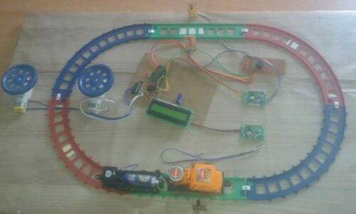
The Final Project Looks Like
Thanks for visiting, hope you understand the project well. Please do check out more Arduino tutorials.
HAPPY LEARNING !!