
Table of Contents
Introduction
Hey geeks, we are back with another new post on Arduino UNO. In this article we are going to teach you that how you can make your own arduino servo control remote system. We are using an IR remote control for sending the signals wirelessly and at the other end we connect a TSOP IR receiver module. For control servo motor you just need to press a button on the IR remote. You can also read more articles on IoT and basic electronics. Make the connections properly and upload the code according.
Description
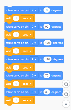
- Initially, the servo motor is in the 0 position.
- When you press the buttons on the IR remote the arduino servo control will start changing its position.
- The positions and their respective codes are already mentioned in the code, you can change the values of different positions as per your need.
- For example, if you press button 1 on the IR remote then the servo motor will rotate to a specific position.
- This is the simplest circuit for this project. Now we connected some LED with the Arduino and this time when you press the buttons of the IR remote, corresponding LED will also turn on automatically.
- The purpose of adding LEDs to the circuit is that so you can see wherethere signal is received by Arduino or not.
- For the third circuit we add an LCD module, now you can see the values received by the Arduino.
- You can also check the Arduino IR remote control made by us.
Components Required for Arduino with Servo Control system
A list of the required components is given below. Make sure that the components are working properly and of the correct values.
- Arduino UNO
- TSOP IR reciever
- Servo motor
- IR remote
- LEDs of three different colors
- 16×2 LCD
- 10K potentiometer
- Jumper wires and a breadboard
- 220 ohms resistors
- USB cable for uploading the code
Circuit for arduino servo control
There are three circuit diagrams given in this post so that you can make any of them as per your choice. Make sure that all the connections are correct and tight. Use breadboard for making the common connections as shown in the diagrams.
Only with Servo motor

- Connect the positive power leg of the TSOP IR receiver with the 5 volts pin of the Arduino.
- Then join the negative power leg with the GND pin of the Arduino.
- After that attach the OUT leg of the IR receiver with the digital-4 pin of the Arduino.
- For the servo motor, connect the VCC wire with the 5 volts pin of the Arduino.
- Join the GND wire with the GND pin of the Arduino. Connect the signal wire of the servo motor with the digital-3 pin of the Arduino in this remote control servo. Your connections are complete now.
Servo motor Arduino code
#include <IRremote.h>
#include <Servo.h>
Servo s1;

int RECV_PIN = 4;
int S ;

IRrecv irrecv(RECV_PIN);

decode_results results;

void setup()
{
  Serial.begin(9600);
  s1.attach(3);
  Serial.println("Enabling IRin");
  irrecv.enableIRIn();
  Serial.println("Project Started");

   s1.write(0);

}

void loop()
{
  if (irrecv.decode(&results))

  {
    S = results.value, HEX ;

    Serial.println(S);
    irrecv.resume(); // Receive the next value

  }

   if(S == 2295 )
  {
      s1.write(90);

  }

    if(S == -30601 )
  {
       s1.write(180);

  }

    if(S == 18615 )
  {
        s1.write(120);

  }

    if(S == 10455 )
  {
        s1.write(70);

  }

   if(S == -22441 )
  {
        s1.write(0);

  }
  delay(10);
}
arduino With LEDs and Servo Motor
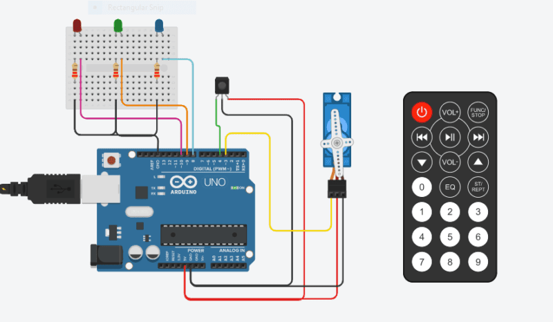
- Join the VCC wire of the servo motor with the 5 volts pin of the Arduino.
- Connect the GND wire of the servo motor with the GND pin of the Arduino.
- Attach the positive power leg of the TSOP IR receiver with the 5 volts pin of the Arduino.
- Then connect the negative power leg with the GND pin of the Arduino.
- After that join the OUT leg of the IR receiver with the digital-4 pin of the Arduino.
- Connect the signal wire of the servo motor with the digital-3 pin of the Arduino.
- Take an LED and join its positive leg with the digital-8 pin of the Arduino. Join the positive leg of the second LED with the digital-9 pin of the Arduino.
- Attach the positive leg of the third LED with the digital-10 pin of the Arduino.
- Connect the negative legs of all three LEDs with the GND pin of the Arduino via a 220 ohm resistor.
- Your connections are complete now.
servo motor arduino code with IR remote
#include <IRremote.h>
#include <Servo.h>
Servo s1;

int RECV_PIN = 4;
int S ;

IRrecv irrecv(RECV_PIN);

decode_results results;

void setup()
{
  Serial.begin(9600);
  s1.attach(3);
  Serial.println("Enabling IRin");
  irrecv.enableIRIn();
  Serial.println("Project Started");

   pinMode(8,OUTPUT);
   pinMode(9,OUTPUT);
   pinMode(10,OUTPUT);
   s1.write(0);

}

void loop()
{
  if (irrecv.decode(&results))

  {
    S = results.value, HEX ;

    Serial.println(S);
    irrecv.resume(); // Receive the next value

  }

   if(S == 2295 )
  {
      s1.write(90);
     digitalWrite(8,HIGH);
     digitalWrite(9,LOW);
     digitalWrite(10,LOW);

  }

    if(S == -30601 )
  {
       s1.write(180);
      digitalWrite(8,LOW);
      digitalWrite(9,HIGH);
      digitalWrite(10,LOW);

  }

    if(S == 18615 )
  {
        s1.write(60);
        digitalWrite(8,LOW);
        digitalWrite(9,LOW);
        digitalWrite(10,HIGH);
  }

    if(S == 10455 )
  {
        s1.write(0);
        digitalWrite(8,LOW);
        digitalWrite(9,LOW);
        digitalWrite(10,LOW);

  }


  delay(10);
}
Arduino With 16×2 LCD and Servo Motor

- First of all, connect the OUT leg of the IR receiver with the digital-4 pin of the Arduino.
- Take an LED and join its positive leg with the digital-8 pin of the Arduino.
- Then attach the positive leg of the second LED with the digital-9 pin of the Arduino.
- Connect the positive leg of the third LED with the digital-10 pin of the Arduino.
- After that connect the negative legs of all three LEDs with the GND pin of the Arduino via a 220 ohm resistor as shown above.

- Now make the connections between the 16×2 LCD module and analog pins of the Arduino.
- For reference, you can read our article on interfacing between LCD and Arduino.
- Connect 10K potentiometer as shown in the image.

- Join the positive power leg of the TSOP IR receiver with the 5 volts pin of the Arduino.
- Then attach the negative power leg with the GND pin of the Arduino.
- Connect the VCC wire of the servo motor with the 5 volts pin of the Arduino and the GND wire of the servo motor with the GND pin of the Arduino.
- Then Connect the signal wire of the servo motor with the digital-3 pin of the Arduino.
- Your connections are complete now.
Arduino With 16×2 LCD and Servo Motor
#include <IRremote.h>
#include <Servo.h>
#include "LiquidCrystal.h"
LiquidCrystal lcd(A0, A1, A2, A3, A4, A5);
Servo s1;

int RECV_PIN = 4;
int S ;

IRrecv irrecv(RECV_PIN);

decode_results results;

void setup()
{
  Serial.begin(9600);
  s1.attach(3);
  lcd.begin(16,2);
  Serial.println("Enabling IRin");
  irrecv.enableIRIn();
  Serial.println("Project Started");

   pinMode(8,OUTPUT);
   pinMode(9,OUTPUT);
   pinMode(10,OUTPUT);
   s1.write(0);

   lcd.setCursor(0,0);
   lcd.print("TECHATRONIC.COM   ");
   delay(2000);

   lcd.setCursor(0,0);
   lcd.print("TV REMOTE PROJECT  ");

}

void loop()
{
  if (irrecv.decode(&results))

  {
    S = results.value, HEX ;

    Serial.println(S);
    irrecv.resume(); // Receive the next value

  }

   if(S == 2295 )
  {
      s1.write(90);
     digitalWrite(8,HIGH);
     digitalWrite(9,LOW);
     digitalWrite(10,LOW);
     lcd.setCursor(0,1);
     lcd.print("90 Dgree B led   ");

  }

    if(S == -30601 )
  {
       s1.write(180);
      digitalWrite(8,LOW);
      digitalWrite(9,HIGH);
      digitalWrite(10,LOW);
      lcd.setCursor(0,1);
      lcd.print("180 Dgree G led   ");

  }

    if(S == 18615 )
  {
        s1.write(60);
        digitalWrite(8,LOW);
        digitalWrite(9,LOW);
        digitalWrite(10,HIGH);
        lcd.setCursor(0,1);
        lcd.print("60 Dgree R led   ");
  }

    if(S == 10455 )
  {
        s1.write(0);
        digitalWrite(8,LOW);
        digitalWrite(9,LOW);
        digitalWrite(10,LOW);
        lcd.setCursor(0,1);
     lcd.print("0 Dgree led OFF   ");

  }


  delay(10);
}
About the Code
First, we declared the data type of each variable and then assign their values. Then declare the pin modes for each input r output pin that we are using. Take the input from the user in the loop function to continue the process. For performing the specific operations we are using if conditional statement. The statements will execute only if the base condition is true.
Code for Control Servo
Note: Please upload the code to the Arduino. Also, you have to install some libraries like <IRremote.h>, <LiquidCrystal.h> . Check here how to add zip libraries to the Arduino IDE.
We hope that you liked this project and understand it as well. If you have any doubts related to this post then feel free to use the comments section given below. Also, do check out more articles on Arduino and Raspberry pi published by us.
Happy Learning!
Any specific pins for the servo motor in Arduino
always try to use he pwm pins for servo motor