Hello Guys, Today I’m demonstrating another tutorial on Raspberry Pi which is a sound sensor with raspberry pi | Python Tutorial | Digital Value. The sound sensor is very common among beginners and hobbyists to create some basic stuff like VU meter and music reactive led. We’ll also see towards these types of projects, but first, let’s see its basic functioning and code. For better understanding, visit its Arduino tutorial via Sound Sensor Arduino Tutorial. So let’s begin today’s topic.
Sound Sensor
The sound sensor is the same as other sensors like IR and Soil moisture but as always functioning of each sensor is the different but basic structure and design are common. Sound sensors are available in various variants ranging from the basic one built out of LM393 IC to the Sparkfun module. Also, analog and digital sensors differ very much in their function and performance.
In the basic version, LM393 IC is used to amplify the voltage generated by the condenser microphone. The voltage which is generated by the microphone is so small that barely be detected by the Raspberry Pi. If you have an Oscilloscope, then you’ll be familiar with its wave n trig mode. So as to make the voltage in the detectable range, we have to use an amplifier IC like LM393.
The sensor has an onboard LED that glows when sound or noise in the microphone is detected. Also, the module has a potentiometer that can be used to trim the voltage level and range. But in analog value, the continued voltage spikes are generated for projects like VU meter and music reactive LED. We’ll discuss these projects in other tutorials.
Material Required
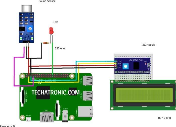
sound sensor with raspberry pi Circuit Diagram

|
Raspberry PI |
Sound Sensor | |
|
GPIO 4 Pin |
D0 | |
|
+5V | +5 V, VCC | |
|
GND |
GND | |
|
Raspberry PI |
16*2 LCD | |
|
GPIO 2 ( SDA ) |
SDA Pin | |
|
GPIO 3 ( SCL ) |
SCL Pin | |
|
+5 Volt |
VCC | |
|
GND |
GND | |
|
Raspberry PI |
LED | 220-ohm Resistor |
|
GPIO 7 Pin |
Anode Terminal ( + ) |
|
|
GND |
|
Terminal 1 |
|
|
Cathode Terminal ( – ) |
Terminal 2 |
Code & Explanation
Explanation
For making code work, first, you have to save some modules in the Raspberry Pi python directory or at the place where you have saved your main code. The required module code is given below copy it and save it with the name LiquidCrystal_I2C.py.
A detailed explanation of all its commands is given in our LiquidCrystal tutorial of Raspberry Pi. do check it for more information. Now let’s move toward the main code. In the main code first, we include some important modules like liquidCrystal_I2C, sleep function from time module & RPi.GPIO module as GP.
Then we set gpio pin numbering board according to the Board convention and set up pin7 as the input pin for the sound sensor. As the Raspberry Pi only has digital pins, so we can only use the digital output of the sound sensor rather than using analog value.
Then we initialize the I2C LCD and create an LCD object with variable name LCD & then give the command to clear any previous data in the memory of the LCD. Then we put some starting string on the LCD screen and then in the while loop we use to try & except to write the continuous main loop.
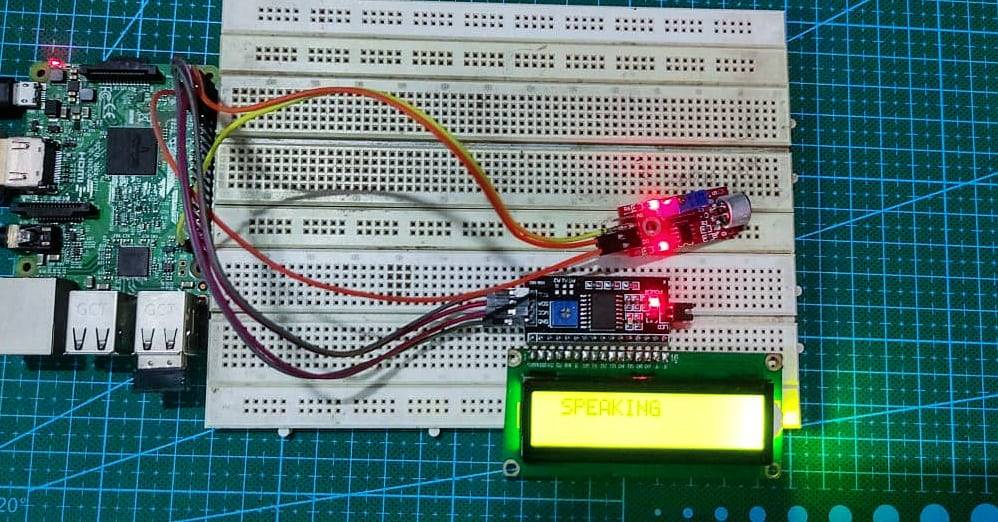
In the while loop we print a string speaking on the LCD screen whenever the input on pin 7 goes high i.e, the sound is detected by the sound sensor.
sound sensor with raspberry pi Code
Required module:
 import smbus
 from time import *
 class i2c_device:
   def __init__(self, addr, port=1):
    self.addr = addr
    self.bus = smbus.SMBus(port)
 # Write a single command
   def write_cmd(self, cmd):
    self.bus.write_byte(self.addr, cmd)
    sleep(0.0001)
 # Write a command and argument
   def write_cmd_arg(self, cmd, data):
    self.bus.write_byte_data(self.addr, cmd, data)
    sleep(0.0001)
 # Write a block of data
   def write_block_data(self, cmd, data):
    self.bus.write_block_data(self.addr, cmd, data)
    sleep(0.0001)
 # Read a single byte
   def read(self):
    return self.bus.read_byte(self.addr)
 # Read
   def read_data(self, cmd):
    return self.bus.read_byte_data(self.addr, cmd)
 # Read a block of data
   def read_block_data(self, cmd):
    return self.bus.read_block_data(self.addr, cmd)
 # LCD Address
 ADDRESS = 0x27
 # commands
 LCD_CLEARDISPLAY = 0x01
 LCD_RETURNHOME = 0x02
 LCD_ENTRYMODESET = 0x04
 LCD_DISPLAYCONTROL = 0x08
 LCD_CURSORSHIFT = 0x10
 LCD_FUNCTIONSET = 0x20
 LCD_SETCGRAMADDR = 0x40
 LCD_SETDDRAMADDR = 0x80
 # flags for display entry mode
 LCD_ENTRYRIGHT = 0x00
 LCD_ENTRYLEFT = 0x02
 LCD_ENTRYSHIFTINCREMENT = 0x01
 LCD_ENTRYSHIFTDECREMENT = 0x00
 # flags for display on/off control
 LCD_DISPLAYON = 0x04
 LCD_DISPLAYOFF = 0x00
 LCD_CURSORON = 0x02
 LCD_CURSOROFF = 0x00
 LCD_BLINKON = 0x01
 LCD_BLINKOFF = 0x00
 # flags for display/cursor shift
 LCD_DISPLAYMOVE = 0x08
 LCD_CURSORMOVE = 0x00
 LCD_MOVERIGHT = 0x04
 LCD_MOVELEFT = 0x00
 # flags for function set
 LCD_8BITMODE = 0x10
 LCD_4BITMODE = 0x00
 LCD_2LINE = 0x08
 LCD_1LINE = 0x00
 LCD_5x10DOTS = 0x04
 LCD_5x8DOTS = 0x00
 # flags for backlight control
 LCD_BACKLIGHT = 0x08
 LCD_NOBACKLIGHT = 0x00
 En = 0b00000100 # Enable bit
 Rw = 0b00000010 # Read/Write bit
 Rs = 0b00000001 # Register select bit
 class lcd:
   #initializes objects and lcd
   def __init__(self):
    self.lcd_device = i2c_device(0x3f)
    self.lcd_write(0x03)
    self.lcd_write(0x03)
    self.lcd_write(0x03)
    self.lcd_write(0x02)
    self.lcd_write(LCD_FUNCTIONSET | LCD_2LINE | LCD_5x8DOTS | LCD_4BITMODE)
    self.lcd_write(LCD_DISPLAYCONTROL | LCD_DISPLAYON)
    self.lcd_write(LCD_CLEARDISPLAY)
    self.lcd_write(LCD_ENTRYMODESET | LCD_ENTRYLEFT)
    sleep(0.2)
   # clocks EN to latch command
   def lcd_strobe(self, data):
    self.lcd_device.write_cmd(data | En | LCD_BACKLIGHT)
    sleep(.0005)
    self.lcd_device.write_cmd(((data & ~En) | LCD_BACKLIGHT))
    sleep(.0001)
   def lcd_write_four_bits(self, data):
    self.lcd_device.write_cmd(data | LCD_BACKLIGHT)
    self.lcd_strobe(data)
   # write a command to lcd
   def lcd_write(self, cmd, mode=0):
    self.lcd_write_four_bits(mode | (cmd & 0xF0))
    self.lcd_write_four_bits(mode | ((cmd << 4) & 0xF0))
   # write a character to lcd (or character rom) 0x09: backlight | RS=DR<
   # works!
   def lcd_write_char(self, charvalue, mode=1):
    self.lcd_write_four_bits(mode | (charvalue & 0xF0))
    self.lcd_write_four_bits(mode | ((charvalue << 4) & 0xF0))
   # put string function
   def display_line(self, string, line):
    if line == 1:
      self.lcd_write(0x80)
    if line == 2:
      self.lcd_write(0xC0)
    if line == 3:
      self.lcd_write(0x94)
    if line == 4:
      self.lcd_write(0xD4)
    for char in string:
      self.lcd_write(ord(char), Rs)
   # clear lcd and set to home
   def clear(self):
    self.lcd_write(LCD_CLEARDISPLAY)
    self.lcd_write(LCD_RETURNHOME)
   # define backlight on/off (lcd.backlight(1); off= lcd.backlight(0)
   def backlight(self, state): # for state, 1 = on, 0 = off
    if state == 1:
      self.lcd_device.write_cmd(LCD_BACKLIGHT)
    elif state == 0:
      self.lcd_device.write_cmd(LCD_NOBACKLIGHT)
   # add custom characters (0 - 7)
   def lcd_load_custom_chars(self, fontdata):
    self.lcd_write(0x40);
    for char in fontdata:
      for line in char:
       self.lcd_write_char(line)
   # define precise positioning (addition from the forum)
   def display(self, string, line, pos):
   if line == 1:
    pos_new = pos
   elif line == 2:
    pos_new = 0x40 + pos
   elif line == 3:
    pos_new = 0x14 + pos
   elif line == 4:
    pos_new = 0x54 + pos
   self.lcd_write(0x80 + pos_new)
   for char in string:
    self.lcd_write(ord(char), Rs)
Save this with LiquidCrystal_I2C.py
Here is the main code:
 import LiquidCrystal_I2C
 from time import sleep
 import RPi.GPIO as gp
 gp.setmode(gp.BOARD)
 gp.setup(7,gp.IN)
 lcd=LiquidCrystal_I2C.lcd()
 lcd.clear()
 lcd.display("Initiating Mic...",1,0)
 sleep(1)
 lcd.display("Listening",2,4)
 sleep(1)
 while True:
   try:
     while(gp.input(7)==1):
       print("SPEAKING...")
       lcd.display("SPEAKING",1,1)
     else:
       lcd.clear()
   except KeyboardInterrupt:
     gp.cleanup()
     break
With this, we have completed our Tutorial on the Sound sensors with Raspberry Pi.
