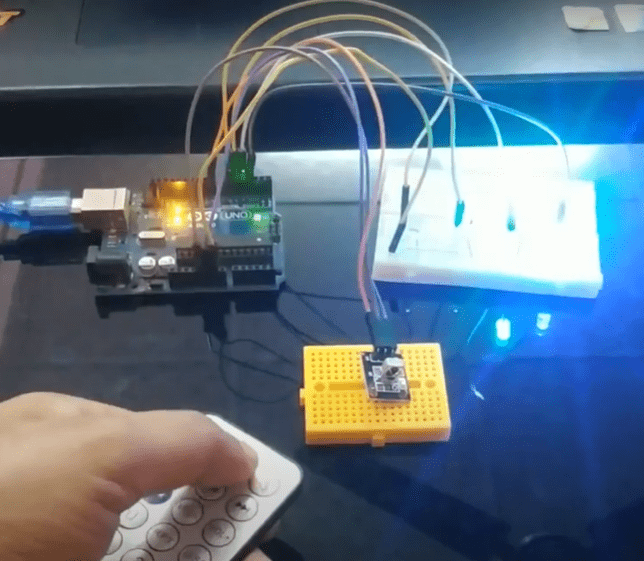
Welcome back to Techatronic. Hey guys in this article we will learn how to make Arduino IR Remote Using TSOP Sensor Module. If you are new to this field and want to explore more cool projects on Arduino, please click here. We use a TSOP sensor module for receiving the IR signals. You can use a T.V, radio, or any other kind of IR remote for sending the signals. IR technology is widely used in today’s world for manufacturing various products such as night vision cameras. The IR communication is working on wireless data transfer technology. The proximity sensor also uses an infrared transmitter and receiver for its operation. There are many variants of Arduino board available in the market but we use Arduino UNO for this project. Basically, Arduino is a microcontroller that operates on Atmega328p IC. You can also check Arduino IR Remote Control Project. You have to make the circuit according to the given circuit diagram and then upload the Arduino code which is also provided below.
How Does it Work?
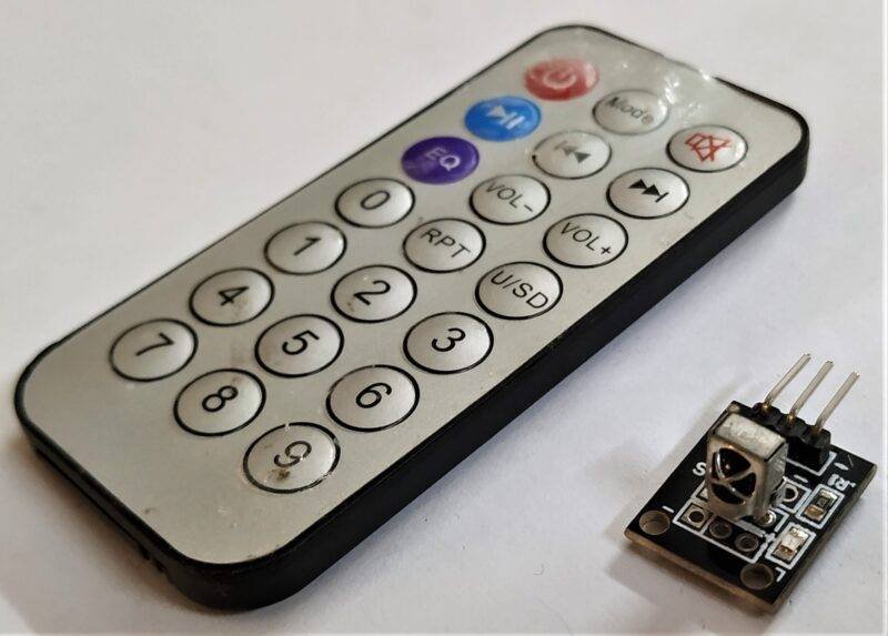
The TSOP sensor module is controlled with the help of Arduino. The information or codes which are received by it is printed on the Arduino IDE serial monitor screen. same as you use an IR remote to control a T.V, home theater, car stereo, etc we use the remote here for sending the information. You can also use a small remote which comes along with this module or you can also buy it. In this IR data transmission technology, you must hold the remote in front of the TSOP sensor module in such a way that both facing each other. The receiver fails to receive any signal if there is an obstacle present in between the receiver and transmitter module. Once you complete the circuit and upload the given code, you have to turn the face of the remote having IR LED towards the TSOP sensor module and then press the buttons on it.
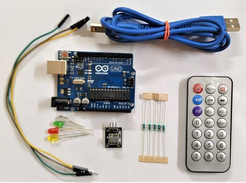
Components Required
- Arduino UNO
- USB cable for uploading the code
- TSOP sensor module
- Jumper wires
- DC adapter to power the Arduino
- Led
- 220-ohm resistor
- Breadboard
| Arduino UNO | BUY LINK |
| USB cable for uploading the code | BUY LINK |
| TSOP sensor module | BUY LINK |
| Jumper wires | BUY LINK |
| DC adapter to power the Arduino | BUY LINK |
| Led | BUY LINK |
| 220-ohm resistor | BUY LINK |
| Breadboard | BUY LINK |
Please download Arduino-IRremote-master (1)
Circuit Diagram

| Arduino UNO | TSOP Sensor ( IR Remote Sensor ) |
| D12 Pin | S Pin (signal Pin ) |
| ( +5V ) vcc | ( + ) ( Positive ) |
| GND | ( – ) ( Negative ) |
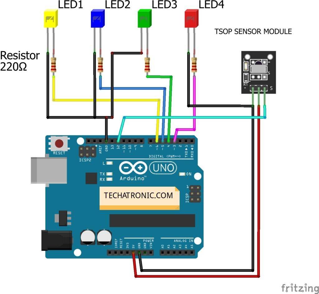
| Arduino UNO | TSOP Sensor ( IR Remote Sensor ) | ||||
| D12 Pin | S Pin | ||||
| +5V | (+) | ||||
| GND | ( – ) | ||||
| Arduino | LED R | LED G | LED B | LED Y | 220 Ohm Resistor |
| D3 Pin | Anode | ||||
| D4 Pin | Anode | ||||
| D5 Pin | Anode | ||||
| D6 Pin | Anode | ||||
| GND | Terminal 1 | ||||
| Cathode | Cathode | Cathode | Cathode | Terminal 2 |
Make the circuit diagram according to the above circuit diagram. You can use a USB cable or a 5-volt DC adapter to power the Arduino. Connect the VCC pin of the TSOP sensor module to the 5-volt pin of the Arduino and GND of the TSOP sensor module to the GND pin of the Arduino. Attach the data pin of the TSOP sensor module to the digital 12 pin of the Arduino. Your receiver circuit is ready. Now upload the Arduino code given below.
Code of the Project
NOTE: Please upload the Arduino code which is provided below as it is using the Arduino IDE application. You have to install <IRremote.h> for working of the IR sensor.
 // TECHATRONIC.COM
 // IR LIBRARY LINK
 // https://github.com/Arduino-IRremote/Arduino-IRremote
 #include <IRremote.h>
 int RECV_PIN = 12;
 int val ;
 IRrecv irrecv(RECV_PIN);
 decode_results results;
 void setup()
 {
  Serial.begin(9600);
  irrecv.enableIRIn();
  Serial.println("Enabled IRin");
 }
 void loop()
 {
  if (irrecv.decode(&results))
  {
   val = results.value, HEX ;
   Serial.println(val); // Print the value in serial monitor
   irrecv.resume();   // Receive the next value
  }
  delay(10);
 }
Another code for LED automation.
 // TECHATRONIC.COM
 // IR LIBRARY LINK
 // https://github.com/Arduino-IRremote/Arduino-IRremote
 #include <IRremote.h>
 int val1=0; // Inializing the variable for storing the last status of Relay_pins
 int val2=0;
 int val3=0;
 int val4=0;
 int RECV_PIN = 8;
 int Data ;
 IRrecv irrecv(RECV_PIN);
 decode_results results;
 void setup()
 {
  Serial.begin(9600);
  // In case the interrupt driver crashes on setup, give a clue
  // to the user what's going on.
  Serial.println("Enabling IRin");
  irrecv.enableIRIn(); // Start the receiver
  Serial.println("Enabled IRin");
  pinMode(3,OUTPUT); // LED 1
  pinMode(4,OUTPUT); // LED 2
  pinMode(5,OUTPUT); // LED 3
  pinMode(6,OUTPUT); // LED 4
 }
 void loop() {
  if (irrecv.decode(&results))
  {
   Data = results.value, HEX ;
   Serial.println(Data);
   irrecv.resume(); // Receive the next value
   if(Data==18615)
   {
    val1=digitalRead(3);
    if(val1==0)
    {
     digitalWrite(3,HIGH);
     val1=1;
     delay(500);
    }
    else
    {
    digitalWrite(3,LOW);
    val1=0;
    delay(100);
    }
   }
   if(Data==22695)
   {
    val2=digitalRead(4);
    if(val2==0)
    {
     digitalWrite(4,HIGH);
     val2=1;
     delay(500);
    }
    else
    {
    digitalWrite(4,LOW);
    val2=0;
    delay(100);
    }
   }
   if(Data==30855)
   {
    val3=digitalRead(5);
    if(val3==0)
    {
     digitalWrite(5,HIGH);
     val3=1;
     delay(500);
    }
    else
    {
    digitalWrite(5,LOW);
    val3=0;
    delay(100);
    }
   }
   if(Data==-32641)
   {
    val4=digitalRead(6);
    if(val4==0)
    {
     digitalWrite(6,HIGH);
     val4=1;
     delay(500);
    }
    else
    {
    digitalWrite(6,LOW);
    val4=0;
    delay(100);
    }
   }
  }
  delay(100);
 }
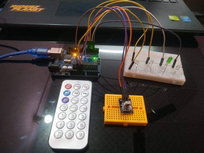
Hope you understand the project well and if you are facing any errors please do inform us in the comments section below. You can also check out more Arduino Tutorials.
HAPPY LEARNING!


