Welcome to Techatronic, in this article will learn how to make Facial Expression on 8X8 LED Matrix Using Arduino. In this project, we use an 8X8 LED Matrix for making different facial expressions on it such as smiling, sed, and neutral face. If you are new to this field please do check out more projects on Arduino. Arduino is a microcontroller that uses ATmega328p IC for its functioning. There are many types of Arduino boards available in the market but we use Arduino UNO for this project. You can also check ws2811 Arduino pixel Led Programming. We can also display long information by using the matrix in the form of moving text. The LED matrix comes in different sizes and also in different colors. Make the circuit as shown below and then upload the given Arduino code. Connect the power supply to the Arduino so the matrix starts displaying the content.
How Does it Work?
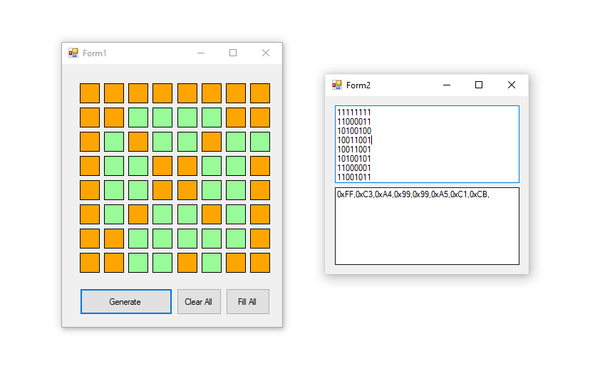
The 8X8 LED matrix is a combination of various LEDs on a single board. This matrix is used to design visual displays. We can make various patterns, text, or some other display stuff with it. There is a total of 64 numbers of LEDs in a single matrix module. All the LEDs are common in Anode and cathode with each other in a pattern. You can also check the Seven segment display with Arduino. There are eight rows and eight columns of LED. We have to specify the location of the LED which we want to turn on in the form of its row and column. We can control the LEDs with the help of the Arduino in the form of rows and columns as given in the picture. To control an individual LED, you have to set its column LOW and its row HIGH. In this project, we display three different facial expressions which repeated themselves at different time intervals. The brightness of the matrix is also adjustable according to one’s choice.
Please check Pixeltomatrix.
Components Required
- Arduino UNO
- USB Cable for Uploading the Code
- 8X8 LED Matrix
- Jumper Wires
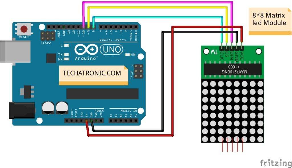
Circuit Diagram of the Project
Make the circuit according to the circuit diagram given above. You can use the USB cable to power the Arduino. Connect the 5-volt pin of the Arduino to the VCC of the matrix and the GND of the Arduino to the GND of the matrix. Attach the DIN pin of the matrix to the digital 10 pin of the Arduino. Join the CS pin of the matrix to the digital 9 pin of the Arduino. Attach the CLK pin of the matrix to the digital 8 pin of the Arduino. After completing the circuit please upload the Arduino code which is given below.
Code of the Project
NOTE: Upload the code given below to the Arduino. You have to install <LedControl.h> library for displaying the content on the matrix.
Code a:
 // TECHATRONIC.COM
  // LED CONTROL LIBRARY
  // https://github.com/wayoda/LedControl
 #include <LedControl.h>
 int DIN = 10;
 int CS = 9;
 int CLK = 8;
 LedControl lc=LedControl(DIN,CLK,CS,0);
 void setup(){
  lc.shutdown(0,false);
  lc.setIntensity(0,5);   //Adjust the brightness maximum is 15
  lc.clearDisplay(0);
 }
 void loop(){
   //Facial Expression
   byte smile[8]=  {0x3C,0x42,0xA5,0x81,0xA5,0x99,0x42,0x3C};
   byte neutral[8]= {0x3C,0x42,0xA5,0x81,0xBD,0x81,0x42,0x3C};
   byte sad[8]=  {0x3C,0x42,0xA5,0x81,0x99,0xA5,0x42,0x3C};
 //Facial Expression
   printByte(smile);
   delay(1000);
   printByte(neutral);
   delay(1000);
   printByte(sad);
   delay(1000);
 }
 void printByte(byte character [])
 {
  int i = 0;
  for(i=0;i<8;i++)
  {
   lc.setRow(0,i,character[i]);
  }
 }
Code b:
 // TECHATRONIC.COM
  // LED CONTROL LIBRARY
  // https://github.com/wayoda/LedControl
 #include <LedControl.h>
 int DIN = 10;
 int CS = 9;
 int CLK = 8;
 LedControl lc=LedControl(DIN,CLK,CS,0);
 void setup(){
  lc.shutdown(0,false);
  lc.setIntensity(0,5);   //Adjust the brightness maximum is 15
  lc.clearDisplay(0);
 }
 void loop(){
   //Facial Expression
   byte smile[8]=  {0x3C,0x42,0xA5,0x81,0xA5,0x99,0x42,0x3C};
   byte neutral[8]= {0x3C,0x42,0xA5,0x81,0xBD,0x81,0x42,0x3C};
   byte sad[8]=  {0x3C,0x42,0xA5,0x81,0x99,0xA5,0x42,0x3C};
   //Arrow
   byte arrow_up[8]= {0x18,0x3C,0x7E,0xFF,0x18,0x18,0x18,0x18};
   byte arrow_down[8]= {0x18,0x18,0x18,0x18,0xFF,0x7E,0x3C,0x18};
   //Alternate Pattern
   byte d1[8]= {0xAA,0x55,0xAA,0x55,0xAA,0x55,0xAA,0x55};
   byte d2[8]= {0x55,0xAA,0x55,0xAA,0x55,0xAA,0x55,0xAA};
   //Moving car
   byte b1[8]= {0x00,0x00,0x00,0x00,0x18,0x3C,0x18,0x3C};
   byte b2[8]= {0x00,0x00,0x00,0x18,0x3C,0x18,0x3C,0x00};
   byte b3[8]= {0x00,0x00,0x18,0x3C,0x18,0x3C,0x00,0x00};
   byte b4[8]= {0x00,0x18,0x3C,0x18,0x3C,0x00,0x00,0x00};
   byte b5[8]= {0x18,0x3C,0x18,0x3C,0x00,0x00,0x00,0x00};
   byte b6[8]= {0x3C,0x18,0x3C,0x00,0x00,0x00,0x00,0x18};
   byte b7[8]= {0x18,0x3C,0x00,0x00,0x00,0x00,0x18,0x3C};
   byte b8[8]= {0x3C,0x00,0x00,0x00,0x00,0x18,0x3C,0x18};
 //Moving car
   printByte(b1);
   delay(50);
   printByte(b2);
   delay(50);
   printByte(b3);
   delay(50);
   printByte(b4);
   delay(50);
   printByte(b5);
   delay(50);
   printByte(b6);
   delay(50);
   printByte(b7);
   delay(50);
   printByte(b8);
   delay(50);
 //alternate pattern
   printByte(d1);
   delay(100);
   printByte(d2);
   delay(100);
 //Arrow
   printByte(arrow_up);
   delay(2000);
   printByte(arrow_down);
   delay(2000);
 //Facial Expression
   printByte(smile);
   delay(1000);
   printByte(neutral);
   delay(1000);
   printByte(sad);
   delay(1000);
 }
 void printByte(byte character [])
 {
  int i = 0;
  for(i=0;i<8;i++)
  {
   lc.setRow(0,i,character[i]);
  }
 }
Hope you understand the project well. If you are facing any errors please do inform us in the comment section below.
Please do check out more projects on Arduino.
HAPPY LEARNING!


