
Hey guys, hope you are doing fine. Have you ever seen the circuits of the amplifiers or the home theater that is used for playing the music? Do you want to make the same circuit for playing music? In this article, we are going to make a transistor amplifier using two bc547 transistors to make BJT as an amplifier. The circuit which we are going to discuss is easy to make and required some basic electronics components. You can also check our latest projects on IoT and basic electronics.
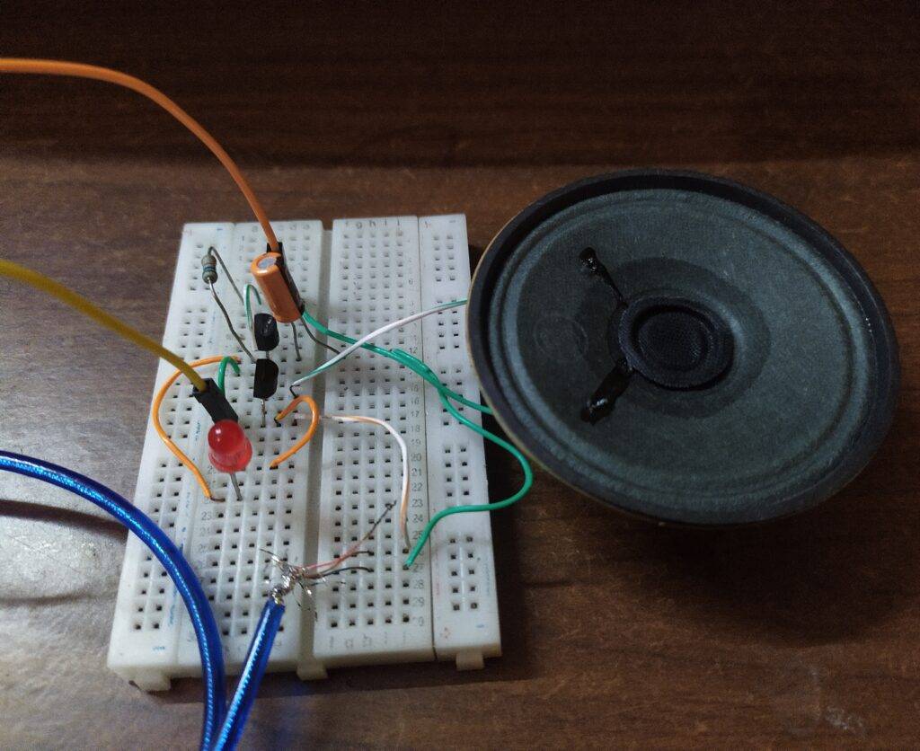
Working transistor amplifier
Amplifiers are of many types such as power amplifier, video amplifier, IF amplifier, current, and voltage amplifier. In this project, we will make an audio amplifier. A transistor amplifier is used to amplify the low input audio signals. We can take the low input signals from the audio jack of smartphones or PCs and convert them into high-quality amplified output signals which are given to an external speaker. An external power supply is also needed to boost up the output audio. This circuit is not much powerful to use at parties but you can use this at your home.

Components Required
| Two BC547 transistors | |
| 1 uF capacitor and a 10K-ohm resistor | BUY LINK |
| AUX cable | |
| Speaker and a 5 volts battery | |
| Connecting wires | BUY LINK |
| Breadboard | BUY LINK |
transistor amplifier Circuit Diagram
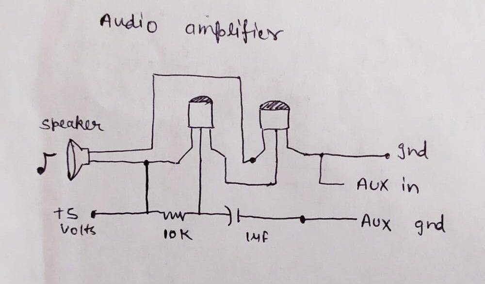
Take two bc547 transistors and connect the emitter pin of the first transistor with the base pin of the second transistor. Connect a 10K-ohm resistor between the base and collector pin of the first transistor. Join the negative wire of the speaker with the collector pin of the first transistor as shown above. Now take a 1 uF capacitor and connect its positive leg with the base pin of the first transistor. Attach the positive wire of the speaker to the collector pin of the second transistor. Peel the covering of an AUX cable and separate the ground and signal wires. You can use a continuity checker or a multimeter for identification purposes. Usually, the ground wire is black and the signal wires are blue and green in many AUX cables. Then connect the ground wire of the AUX cable with the emitter pin of the second transistor and the signal pin of the AUX cable with the negative leg of the capacitor. At last, connect the positive wire of the power supply with the collector pin of the first transistor and the negative wire with the emitter pin of the second transistor.
Let’s test the Audio Amplifier
Connect the AUX cable with your smartphone and play some music on it. The speaker starts playing the sound which is loud and clear. There is no disturbance in the audio. If you find some noise in the audio output, please check whether all the connections are tight.

We are sure that you now gather some knowledge about the working of an audio amplifier. While making this project if you are facing any difficulties then do inform us in the comments section given below. Also, do check out our tutorials on Arduino and Raspberry Pi.
HAPPY LEARNING!