

Welcome to Techatronic. In this article, we will learn how to make a Robotic Arm With Servo Motor Using Arduino. The robotic arm which we make can move in different directions. If you are new to this field and want to explore more cool projects on Arduino please click here. Arduino is a microcontroller whose functioning is controlled by ATmega 328p IC. There are many variants of Arduino available in the market but we use Arduino UNO for this project. We use Servo motors to control the movement of the robotic arm. If you don’t know how to operate a servo motor with Arduino then check it here. We can move the robotic arm in the desired direction with the help of a joystick module. Also, check the interfacing of the Joystick module with Arduino. Please make the circuit according to the circuit diagram and then upload the Arduino code which is provided in the last.
How Does it Work?
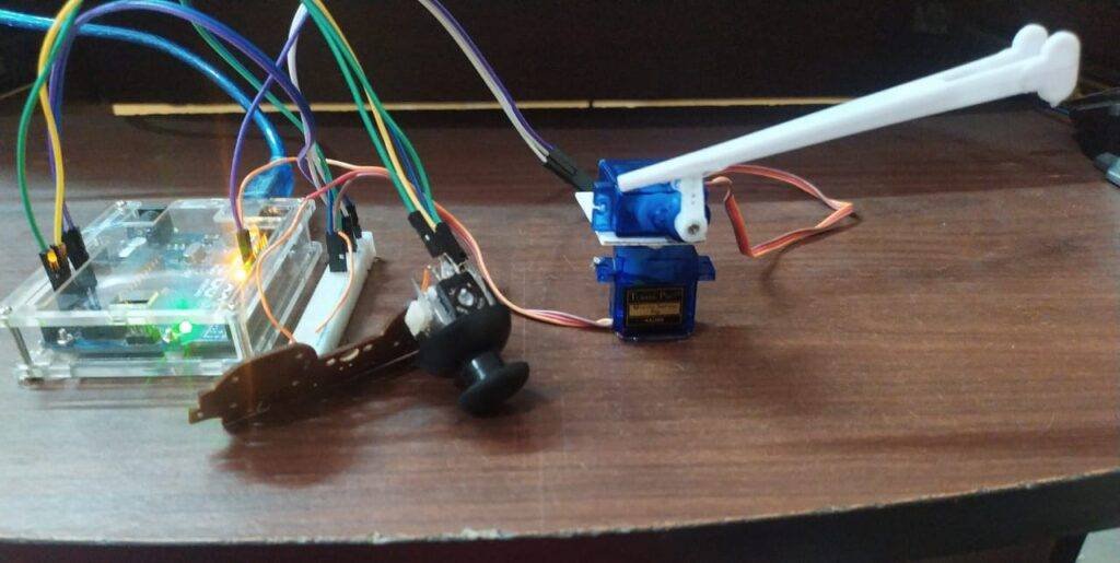
The robotic arm which we make can move in both positive and negative X and Y axis (2-D) with the help of two servo motors. We use the Joystick module for giving the commands. We can control the motion of servo motors through it. Mount one of the servo motors on the other using the attachments or you can also use a cardboard piece such that both can move comfortably in the desired direction. After completing all the procedures just move the Joystick in a random direction and your robotic arm will follow your commands. The benefits of using the Servo motor are that we can easily control its position and the degrees we want it to move. The response of the robotic arm is very quick and you can control it as per your choice.
Components Required
| Arduino UNO | BUY LINK |
| Arduino UNO cable | BUY LINK |
| Jumper wires | BUY LINK |
| Breadboard | BUY LINK |
| Joystick module | BUY LINK |
| 2. servo motors | BUY LINK |
Circuit Diagram
| Arduino UNO | Joystick Module | |
| GND | GND | |
| ( +5V ) | + 5 V | |
| A0 Pin | VRx Pin | |
| A1 Pin | VRy Pin | |
| SW Pin | ||
| Arduino UNO | Servo Motor 1 | Servo Motor 1 |
| D8 Pin | OUT Pin | |
| D9 Pin | OUT Pin ( Orange Colour ) | |
| ( +5V ) | VCC | VCC ( Red Colour ) |
| GND | GND | GND ( Black Colour ) |
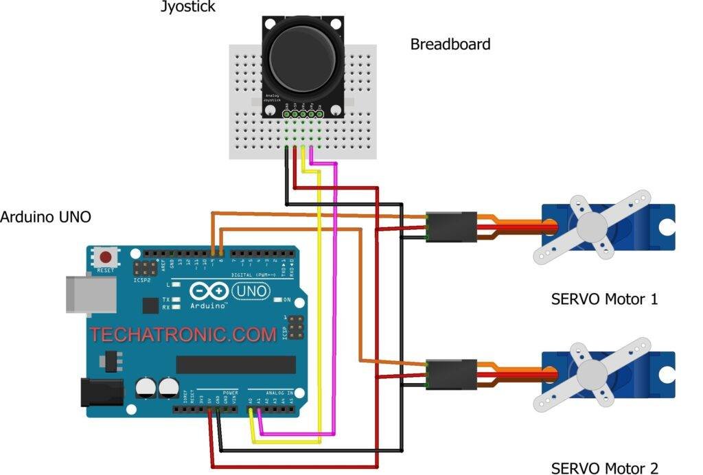
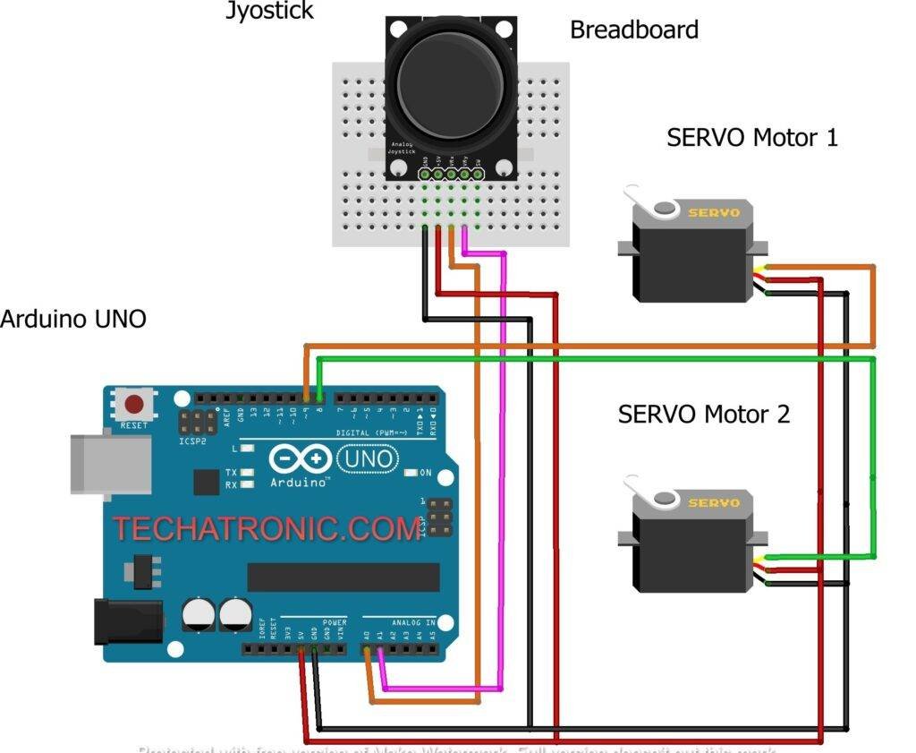
Code for the Robotic ArmMake the connections according to the circuit diagram given above. Connect the positive wires of both the servo motors to the 5-volt pin of the Arduino. Attach the negative wires of both the servo motors to the GND pin of the Arduino. Join the VCC of the Joystick module to the 5-volt pin of the Arduino and the GND pin of the module to the GND pin of the Arduino. Use the breadboard for making these connections and to supply a common 5 volt supply from the Arduino. Connect the servo motors’ data pins to the digital 8 and digital 9 pins of the Arduino. Attach the Vrx pin of the joystick to the analog 0 pin of the Arduino and Vry to the analog 1 pin of the Arduino. Please left the SW pin of the joystick as it is. After completing the circuit upload the given Arduino code.
NOTE: Upload the Arduino code which is given below as it is. You have to install <Servo.h> for the proper working of the project.
 //Techatronic.com
 //Robotic_arm_code
 #include <Servo.h>
 const int servo1 = 8;    // first servo
 const int servo2 = 9;    // second servo
 const int joyx = 0;      // joystick module  A0 pin
 const int joyy = 1;      // joystick module  A1 pin
 int servoVal;      // read the value from the analog pin
 Servo myservo1; // create servo object to control a servo
 Servo myservo2;
 void setup() {
  Serial.begin(9600);
  myservo1.attach(servo1);
  myservo2.attach(servo2);
 }
 void loop(){
   servoVal = analogRead(joyx);
   servoVal = map(servoVal, 0, 1023, 0, 180);  // set the position of the first servo
   myservo2.write(servoVal);
   servoVal = analogRead(joyy);
   servoVal = map(servoVal, 0, 1023, 70, 180);   // set the position of the second servo
   myservo1.write(servoVal);
   delay(15);
 }
Hope you understand the project well. If you are facing any errors please do inform us in the comments section below.
HAPPY LEARNING!