
Hi Guys, Today We Will Discuss Another Interesting And Important Module Interfacing With Arduino.Simply First We Will Understand About The Joystick. Then Understand Interfacing Joystick with Arduino in this article.
What Is The Joystick, how it works?
Joystick Is Basically Input Device That Will Be Used TO Control The Robotics And It Has Been Also Used In Gaming. The Construction Image Of The Joystick As Shown In Above Fig. The Joystick Are Different Types And Uses In Different Purposes. The Above Images Shows The Pins That Will Be Used For Interfacing With Hardware. We Know About The First Two Pin That Is Basic Pins Which Is Used In Every Hardware. That Is +5V And Another Is Ground. Another Three Pins Are Input And Output Pins. The VRx And VRy Are The Input Pin And SW Is The Output Pines Will Briefly Understand About The Interfacing Joystick With Arduino.
Basically, The Whole Working Of The Joystick Is Based On The Axis’s Movement Shown In Below Fig.
We Have Seen In This Image The VRx And VRy Generated The Different Value In Different Position So This Value Will Be Important For Our Hardware For Next Command.

Components Required
| Arduino UNO | BUY LINK |
| USB Cable for Uploading the Code | BUY LINK |
| Joystick Module | BUY LINK |
| LED | BUY LINK |
| 220-ohm resistor | BUY LINK |
| Jumper Wires | BUY LINK |
| Breadboard | BUY LINK |

Controlling LED’S using a joystick/Arduino joystick controller

| Arduino UNO | Joystick Module | |||||
| A0 Pin | VR X Pin | |||||
| A1 Pin | VR Y Pin | |||||
| D2 Pin | SW Pin | |||||
| ( +5V ) VCC | VCC | |||||
| GND | GND | |||||
| Arduino | LED B | LED G | LED R | LED W | LED Y | 220 Ohm Resistor |
| D10 Pin | Anode | |||||
| D9 Pin | Anode | |||||
| D8 Pin | Anode | |||||
| D7 Pin | Anode | |||||
| D6 Pin | Anode | |||||
| GND | Terminal 1 | |||||
| Cathode | Cathode | Cathode | Cathode | Cathode | Terminal 2 |
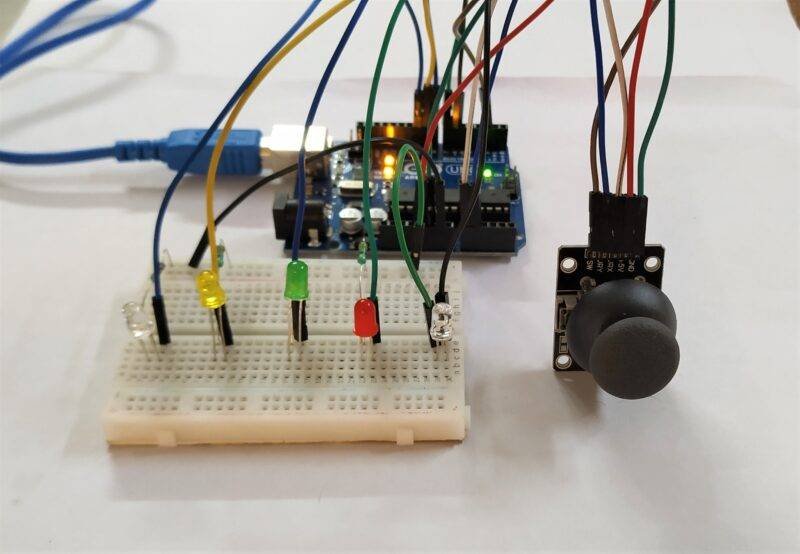
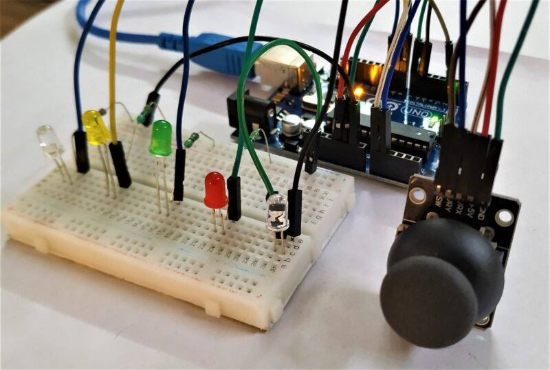
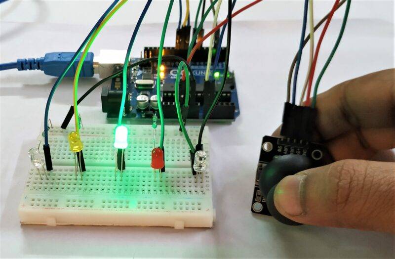
We Understand Practically The LED’S Controlling By The Joystick In The Image Shows The Circuit Connection And Interfacing With Each Other The A0And A1 Is The Analog Pin Of The Arduino Which Will Used Forgiving The Input And SW Specially Used For Command The Output And The Output As Display As LED’S That Basically Work With Moving The Joystick Around The Position Of Nob And And Colorful LED’S Will Glow For The Position Of The Nob That Command Will Have Generated By The Arduino Code Which Is Burn On The Hardware. We Briefly Understand Circuit And Code Below.
Understand The Code And Circuit Briefly.
joystick module arduino Code
 // Techatronic.com
 #define joyX A0
 #define joyY A1
 int button=2;
 int buttonState = 0;
 void setup() {
   pinMode(6,OUTPUT);   // led red pin
   pinMode(7,OUTPUT);   // led green pin
   pinMode(8,OUTPUT);   // led blue pin
   pinMode(9,OUTPUT);   // led white pin
   pinMode(10,OUTPUT);   // led yellow pin
   pinMode(button,INPUT); // Button Pin In Jyostick
   digitalWrite(button, HIGH);
   Serial.begin(9600);
 }
 void loop()
 {
   int xValue = analogRead(joyX);
   int yValue = analogRead(joyY);
   buttonState = digitalRead(button);
   delay(500);
  // See the value in Serial Monitor
   Serial.print("X Value ");//
   Serial.print(xValue);
   Serial.print("\t");    //
   Serial.print("Y Value " );//
   Serial.print(yValue);
   Serial.print("\t");    //
   Serial.print("Button Value ");//
   Serial.println(buttonState);
  if (xValue>=480 && yValue<=10)
  {
   digitalWrite(6, HIGH);
  }
  else
  {
   digitalWrite(6, LOW);
  }
  if (xValue<=10 && yValue>=400)
  {
   digitalWrite(7, HIGH);
  }
  else
   {
   digitalWrite(7, LOW);
   }
  if (xValue>=1020 && yValue<=500)
  {
   digitalWrite(8, HIGH);
  }
  else
   {
   digitalWrite(8, LOW);
   }
  if (xValue>=500 && yValue>=1020)
  {
   digitalWrite(9, HIGH);
  }
  else
   {
   digitalWrite(9, LOW);
   }
  if (buttonState == LOW)
  {
   Serial.println("Switch = High");
   digitalWrite(10, HIGH);
  }
  else
  {
   digitalWrite(10, LOW);
  }
 }
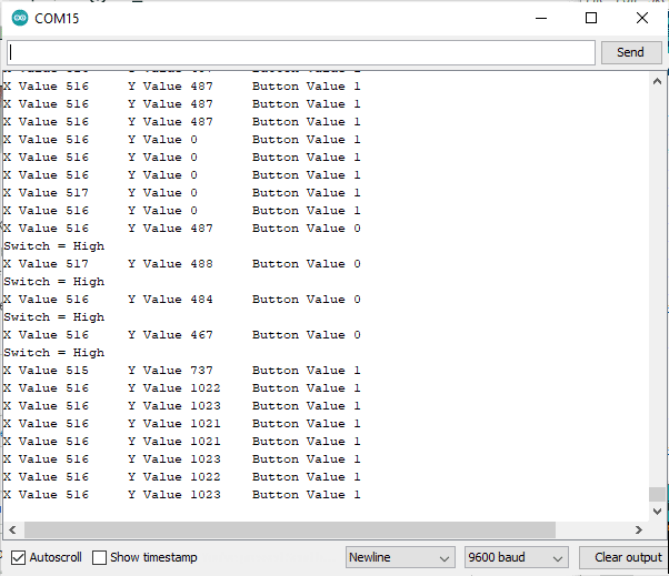
uploading the program then open serial monitor

Firstly Focused On The Point Of The Pin Connection of joystick module arduino And Another See The Code Firstly Initiate The Input That Is Input Is From Joystick That Is Connected To The Arduino Uno Board. And The Another Command Is The SW Is The Button Which Is Used As Command To The Pin No 2. Another In Code We Can Initialize The Pin Mode Of LED’S Which Is Output Of Our Project. The LED’S Are Basically The Output Of Our Circuit In Another And the Main Thing In Code Is High And Lows Command Which Can Get The Result On The LED’S.
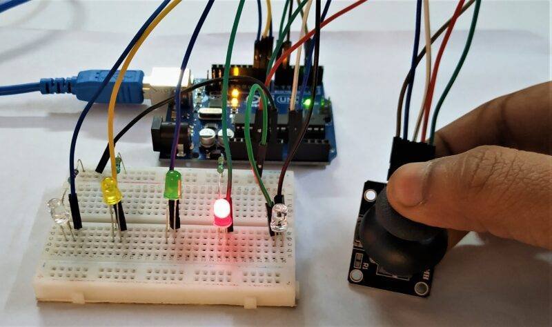
When The Joystick Move Then The Analogue Output Generated And Give TO Our Hardware That Is Arduino, And Then Hardware Accept It And Work Through The Action Of Command. Whole The Working Of The Joystick Are On The Axis Which Is Generated The Specific Value And Hardware Measure It And Give The Output. When The Axis Of The Joystick Will Move Then The Led Will Be Bright Or On On That Operation I Hope You Can Understand The Joystick Arduino Interfacing. Any Other Question Regarding This Topic You Can Ask On Mail Or In Comment Section Our Team Will Give You Perfect Suggestion For That. Thanks’