
Hello Techie. Do you want to know how RC522 RFID Module works? Do you want to create your own DIY project using RC522 RFID with Arduino? well, you are at the right web portal. From this article, you will get all the important and detailed step-by-step guides. Here you will also get the circuit diagram and Arduino code. Hence, I hope you find this useful. We at Techatronic have already uploaded several Arduino Tutorials and detailed project guides related to electronics, embedded & Arduino which will be useful to learn the basics and programming of Arduino.
What is RFID?
RFID stands for Radio Frequency Identification. Various applications such as key cards, Tags inside supermarkets, and much more use this technology on a large scale. RFID is a wireless technology that transmits information over radio waves. in the RFID with Arduino there we power the RFID with Arduino and the RFID card does not need the power to transmit the information. there is a coil inside the RFID card when it comes near to the RFID reader it gets activated through mutual induction. In this period of time, the RFID reader gets information from the card. this is how the combination of both works.
This is also getting popular as a digital replacement for the key as the tags can be easily stored in our wallets and are also available as key chains. Supermarkets use them for security purposes. This can also be used with Arduino in many DIY projects such as Door Security System, RFID based Attendance System, etc. NFC technology also works on the same principle But uses a very high frequency for the communication
How Does RFID Module Work?
Radio Frequency Identification Module as the name suggests requires a Radiofrequency of 13.56 MHz for its working. This Module uses four pins to communicate using the SPI(Serial Peripheral Interface) protocol with a maximum Data rate of 10Mbps.
The module creates an Electromagnetic Field using the coil to communicate with the chip inside the card. Since the card is a passive device, it gets power through the generated Electromagnetic Field. The reader is capable of reading the tags in the vicinity close to some millimeters up to meters on certain conditions. The chip inside the card contains 1kb storage is used to store UID information related to that tag, which can also be used to store some custom data also.
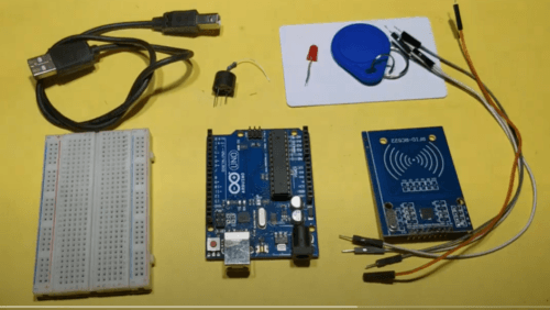
Components Required
| Arduino UNO | BUY LINK |
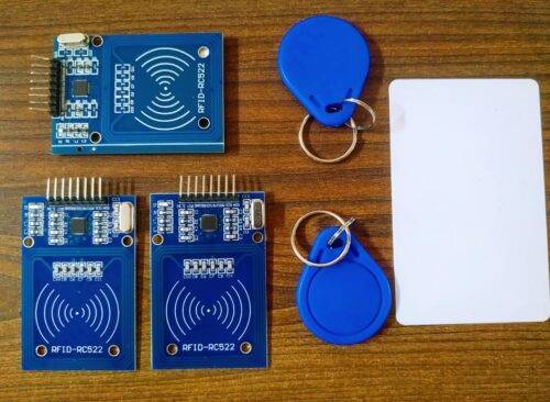
| RC522 RFID Module | BUY LINK |
| Jumper Wires | BUY LINK |
| Breadboard | BUY LINK |
| LED | BUY LINK |
| 220-ohm Resistor | BUY LINK |
| Buzzer | BUY LINK |
| USB Cable to connect Arduino UNO with Computer. | BUY LINK |
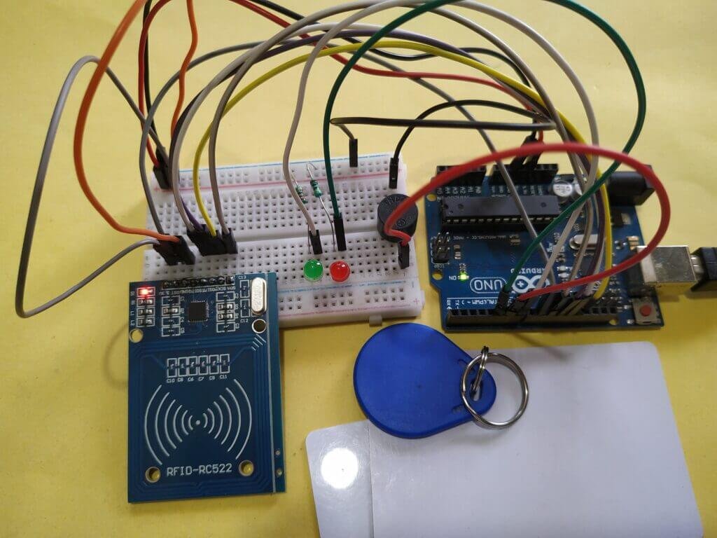
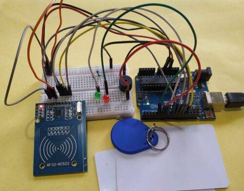
RFID Arduino Tutorial Circuit Diagram
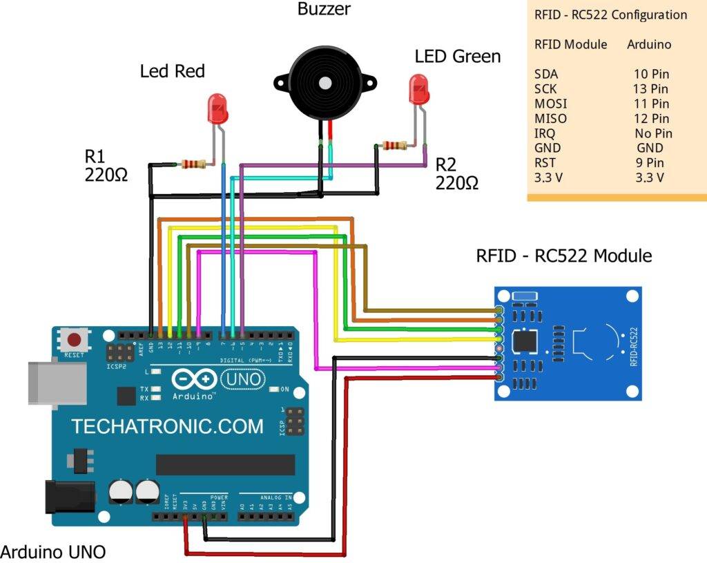
| Arduino UNO | RFID – RC522 Module | ||
| 10 Pin | SDA Pin | ||
| 13 Pin | SCK Pin | ||
| 11 Pin | MOSI Pin | ||
| 12 Pin | MISO Pin | ||
| No Pin | IRQ Pin | ||
| GND | GND | ||
| RST Pin | RST Pin | ||
| 3.3 V | 3.3V | ||
| Arduino UNO | Buzzer | ||
| D6 Pin | Positive Terminal | ||
| GND ( Ground ) | Negative Terminal | ||
| Arduino | LED R | LED G | 220 Ohm Resistor |
| D7 Pin | Anode Pin | ||
| D5 Pin | Anode Pin | ||
| GND | Terminal 1 | ||
| Cathode Pin | Cathode Pin | Terminal 2 |
RFID Arduino Code
// TECHATRONIC.COM
// SPI Library
// https://github.com/PaulStoffregen/SPI
// MFRC522 Library
// https://github.com/miguelbalboa/rfid

#include <SPI.h>
 #include <MFRC522.h>
 #define SS_PIN 10
 #define RST_PIN 9
 #define LED_G 5 //define green LED pin
 #define LED_R 7 //define red LED
 #define BUZZER 6 //buzzer pin
 MFRC522 mfrc522(SS_PIN, RST_PIN); // Create MFRC522 instance.
 void setup()
 {
 Serial.begin(9600); // Initialize serial communications with the PC
 while (!Serial); // Do nothing if no serial port is opened (added for Arduinos based on ATMEGA32U4)
 SPI.begin(); // Init SPI bus
 mfrc522.PCD_Init(); // Init MFRC522
 mfrc522.PCD_DumpVersionToSerial(); // Show details of PCD - MFRC522 Card Reader details
 Serial.println(F("Scan PICC to see UID, SAK, type, and data blocks..."));
 pinMode(LED_G, OUTPUT);
 pinMode(LED_R, OUTPUT);
 pinMode(BUZZER, OUTPUT);
 }
 void loop()
 {
 // Look for new cards
 if ( ! mfrc522.PICC_IsNewCardPresent())
 {
 return;
 }
 // Select one of the cards
 if ( ! mfrc522.PICC_ReadCardSerial())
 {
 return;
 }
 //Show UID on serial monitor
 Serial.print("UID tag :");
 String content= "";
 byte letter;
 for (byte i = 0; i < mfrc522.uid.size; i++)
 {
 Serial.print(mfrc522.uid.uidByte[i] < 0x10 ? " 0" : " ");
 Serial.print(mfrc522.uid.uidByte[i], HEX);
 content.concat(String(mfrc522.uid.uidByte[i] < 0x10 ? " 0" : " "));
 content.concat(String(mfrc522.uid.uidByte[i], HEX));
 }
 Serial.println();
 Serial.print("Message : ");
 content.toUpperCase();
 if (content.substring(1) == "D0 10 22 25")
 //change here the UID of the card/cards that you want to give access
 {
 digitalWrite(LED_G, LOW);
 digitalWrite(LED_R, HIGH);
 delay(500);
 digitalWrite(LED_R, LOW);
 }
 else
 {
 digitalWrite(LED_G, HIGH);
 digitalWrite(LED_R, LOW);
 digitalWrite(BUZZER, HIGH);
 delay(500);
 digitalWrite(LED_G, LOW);
 digitalWrite(BUZZER, LOW);
 }
 }
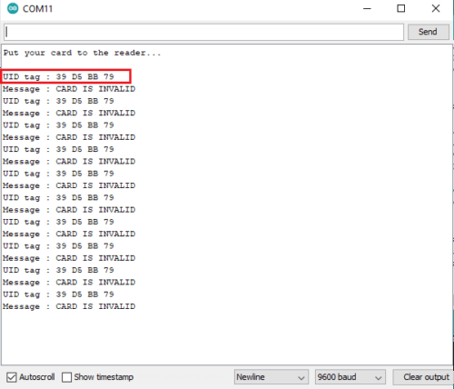
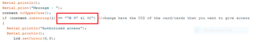
After Uploading the code, take a card and keep it on the module. You need to copy all the required tag IDs and paste them into the code to grant access. I hope you found this article helpful. If you have any queries, you can post them in the comment section below.
Sponsor:

Create a profession looking PCB for this project Just by uploading Gerber files to NextPCB. They provide professional quality looking PCB of 1,2,4 etc. layers of PCB at a very low price. Not just only that they also provide PCB Assembly service with multiple continuity testing, AOI & X-RAy testing. So, don’t just compromise with messy circuits, rather go to NextPCB and Order one for yourself now.