
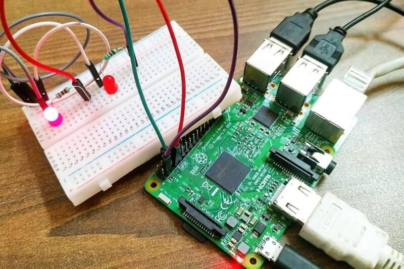
Hello Tech Folks, I am here with you with some of basic tutorials of Raspberry Pi. Today we gonna configure a led and see how we can use Raspberry Pi GPIO pins along with its complete pinout. So let’s continue to our topic. Wait a minute for your convenience, I must tell you that I am using RPI 4B+GB version so try using that or PI 3B+ for better grip on topic.
What is GPIO?
GPIO stands for General Purpose Input Output in shot GPIO. We all are familiar with Arduino boards. If someone is not familiar then look up at our ARDUINO section to get a glimpse of it. I can also make interesting projects on Arduino for that you have to comment me down below. I will surely share few of those with you all . So back on our topic let me introduce you to RPI GPIO Pins for this here is an image of pinout(from official Raspberry Pi page)

also you can view pinout of your version of raspberry pi by typing ‘pinout’ in terminal of your OS. For more information you can visit official page of raspberry pi GPIO by clicking here.
What type pins available?
So now it’s the matter of what type of pins are available in PI GPIO which we can use. So in short except analog pins, you can use any type of communication that you are familiar with arduino. I2C,SPI,UART,Serial and PWM also you can do whatever you want with Pi GPIO pins except using it for analog function. If you want to use analog devices with pi then I’ll make a separate topic for it.
How to program?
Let’s begin our main motive of how to program pi GPIO pins. So first of all you’ll need to open Thonny python (beginners) or if you are familiar with terminal you can also open that. But for saving the program you’ll need Thonny python as it is easy. As for terminal you can also save files using terminal by using ‘ sudo nano’ command but it is some tricky thing for beginners.
so if you have opened any one of it (if terminal than first type ‘python’ to open python terminal or to save file type
 cd Dsektop
 sudo nano try1.py
this command will create a ‘try1’ named python file on the desktop).Aslo by using terminal you have to type this to make file accessible in Thonny python by simply typing
 cd Desktop
 sudo chmod a=rwx try1.py
This will make file read, write and executable for all user.Or for Thonny Pyhton IDE you didn’t need these all things simple click save button on it.
Main CODE:
 import RPi.GPIO as gp
 from time import sleep
If you are a python student from before you might be familiar with this import…..as…… commands or if you aren’t then in simple words. Using this command we import RPi.GPIO library onto or code and name it as gp. You can give any name to it you want but try to use short and easy to understand names.
Next command import sleep command from time module which is import for delaying the flow of program like delay(2000) in Arduino
gp.setmode(gp.BOARD)
OR
gp.setmode(gp.BCM)
Now these two lines determine how your program will map the pins on the pi either by BOARD numbers or by GPIO numbers assigned by BROADCOM (BCM). If you have previously type ‘pinout’ on terminal then you will get to know the difference between the two or here it the picture
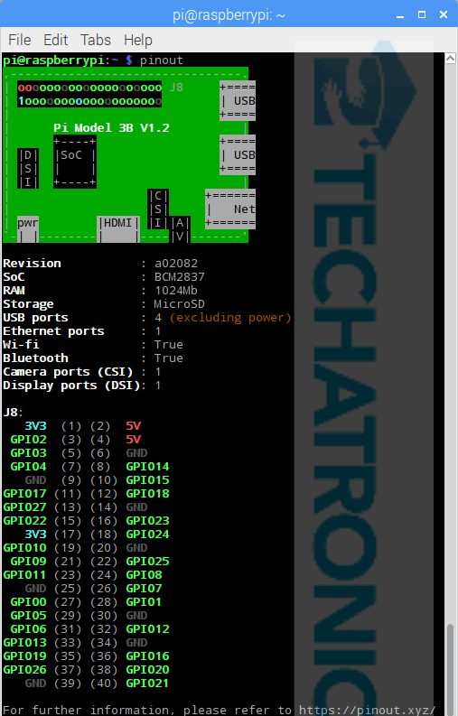 The numbering 1-40 are BOARD numbering and the one with GPIO as prefix are BCM numbering.
NOTE: You can only use dedicated GPIO pins(marked with green color) either in BOARD or BCM mode.
gp.setup(8,gp.OUT)
in BOARD numbering (reffer to above picture for more clarification)
OR
gp.setup(14,gp.OUT)
if you want to assign any intial state to the pin on startup then you can use this statement
gp.setup(8,gp.OUT, initial=gp.LOW)
same as in BCM format
now the main code
gp.output(8,gp.HIGH)
 sleep(1)
 gp.output(8,gp.LOW)
 sleep(1)
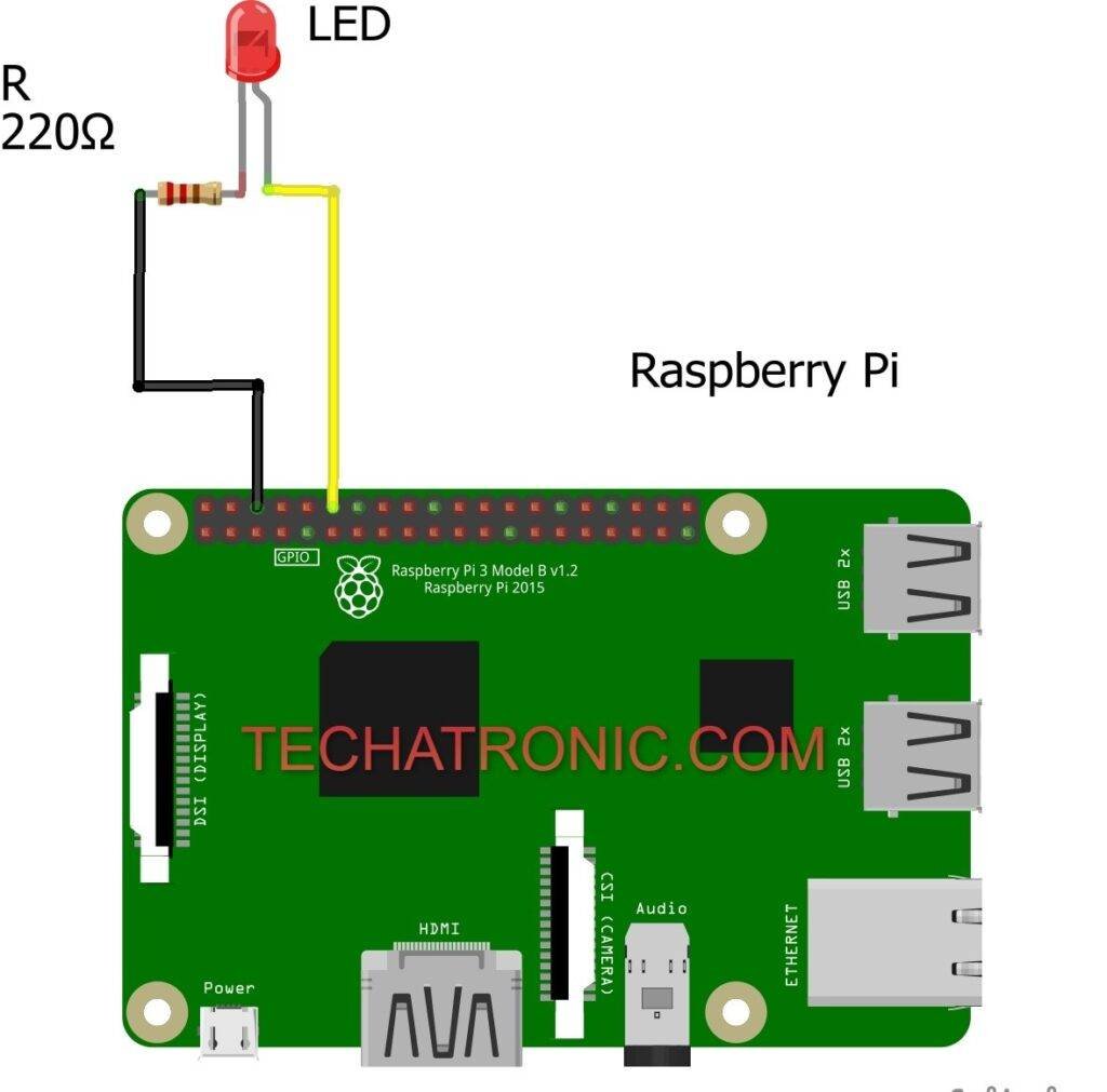
you can also assign the pin no to a variable like in Arduino. By this code you will be able to blink a Led on pin 8 of GPIO pins. Full complete code is here:
import RPi.GPIO as gp
 from time import sleep
 led=8   #assigning the pin number to a variable
 gp.setmode(gp.BOARD)   #setting numbering of GPIO pins by BOARD format
 gp.setup(led,gp.OUT,initial=gp.LOW)   # setting up pin 8 as output with initial pin status as off or LOW
 while True:
      gp.output(led,gp.HIGH)
      sleep(1)   # giving delay of 1s
      gp.output(led,gp.LOW)
      sleep(1)
To stop blinking wither press stop button on Thonny python IDE. Or press Ctrl+C on keyboard to stop. So this first basic tutorial is complete. If you face any issue with it then let me know in comment down below. I’ll surely help you out with. I hope you find this interesting and until then wait for my new post on Raspberry Pi Tutorials.
Sponsor:

So as an electronics hobbyist you may sometimes feel to convert your some project into professional ones. For this purpose, I’ll recommend you to use NextPCB. I personally use their excellent PCB manufacturing service for developing some cool and professional looking PCB for my projects. Also, they provide PCB Assembly service for easiness. Complete multiple testing with AOI and X-Ray testing is done before delivering out PCB to your address. So feel free to use NextPCB service at a reasonable price.