Hello geeks, hope you are doing fine. Have you ever seen a circuit that performs certain activities automatically at a specific time? These types of circuits are called delay timers and can be made in a number of ways.
Table of Contents
Introduction
Here we are going to make a simple on/off 555 delay timer 555 with the help of 555 timer ic. You can adjust the delay time for both on and off circuits by changing the values of resistors and capacitors.
If you want to make this project with us then follow each and every step carefully. Also, do check out more projects on 555 timer ic and Arduino boards. Make the circuit according to the given diagram.
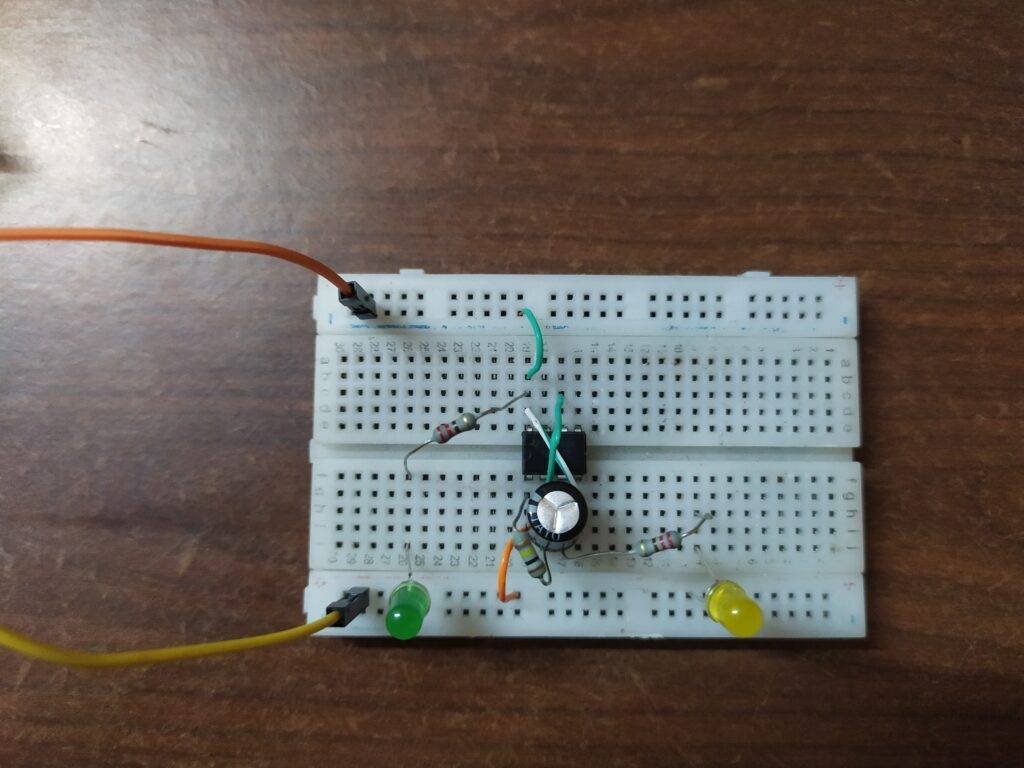
What is a 555 delay timer?
A delay timer is a circuit in which the component that you want to operate starts working after a time delay from the power is turned on. In this project, we have made both on and off delay timers and the individual circuit diagrams are also given below.
Let us first see an On delay timer. For this circuit, the yellow LED that is for output is turned on after a delay of 10 seconds. Initially, the yellow LED is off and then it will be turned on automatically.
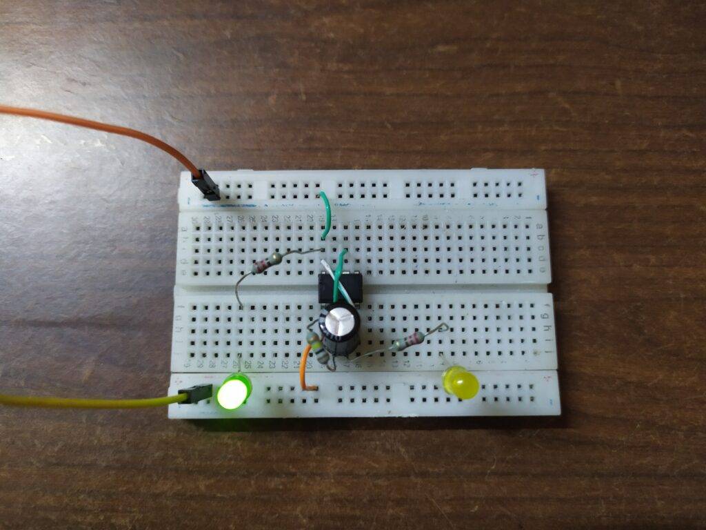
After a delay of 10 seconds, it will be turned on.
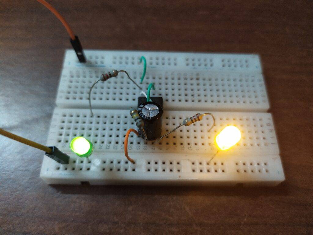
For an OFF delay timer, the output LED is initially on.

Then after a delay of 10 seconds, it will be turned off.
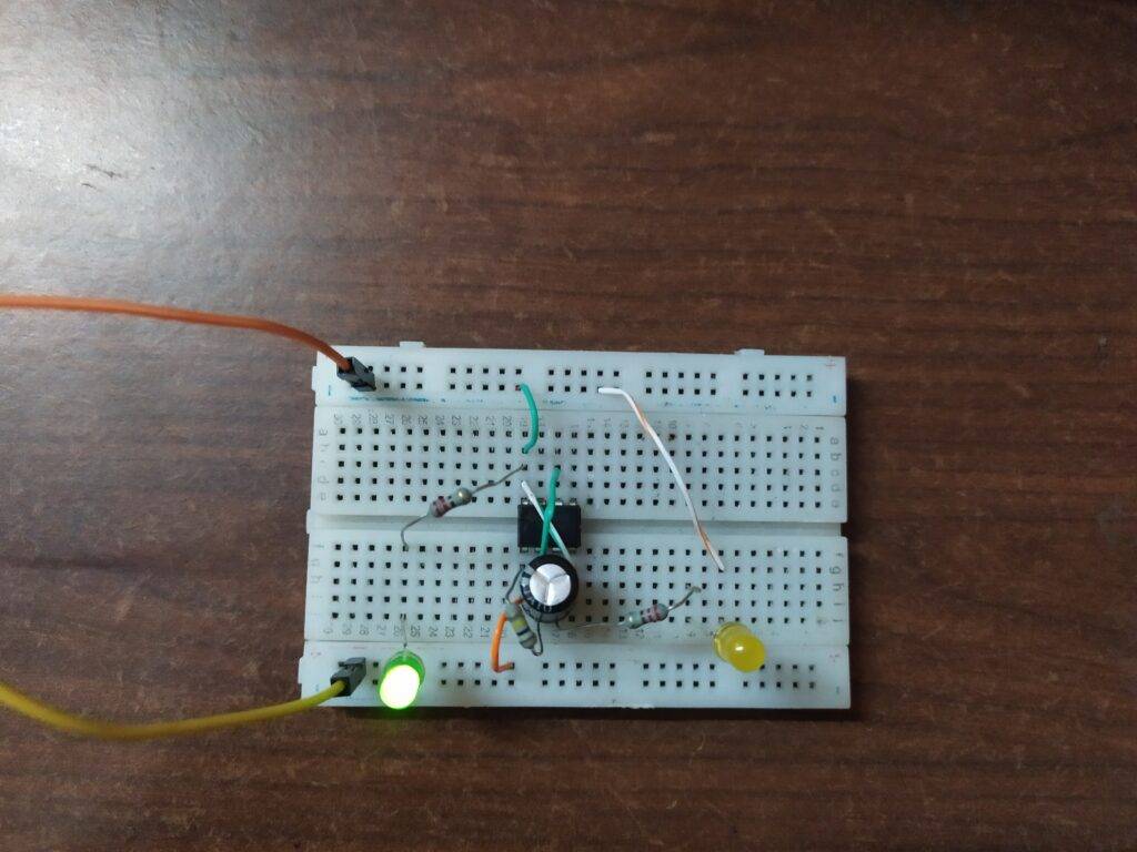
Components Required
| 555 timer ic | |
| Connecting wires | BUY LINK |
| Breadboard | BUY LINK |
| 220-ohm resistor and 100K-ohm resistor | BUY LINK |
| Two LEDs | BUY LINK |
| 100 uf capacitor | |
| 9v battery | BUY LINK |
555 timer delay Circuit Diagram
ON delay timer

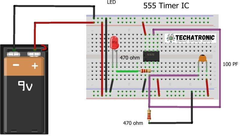
- Connect the reset pin of the ic that is number 4 with the positive rail.
- Join pin 2 and pin 6 of the ic with each other.
- Put a 100K ohm resistor between pin 1 and 2 of the ic.
- Take a 100 uF capacitor and connect its negative leg with pin 2 of the ic and positive leg with the positive rail.
- Attach a 220-ohm resistor between the output pin that is number 3 pin and the positive leg of an LED.
- Join the negative leg of the LED with the negative rail.
- Take another LED and connect its positive leg with the positive rail via a 220-ohm resistor and the negative leg with the negative rail.
- Connect pin 1 with the negative rail and pin 8 with the positive rail.
OFF delay timer
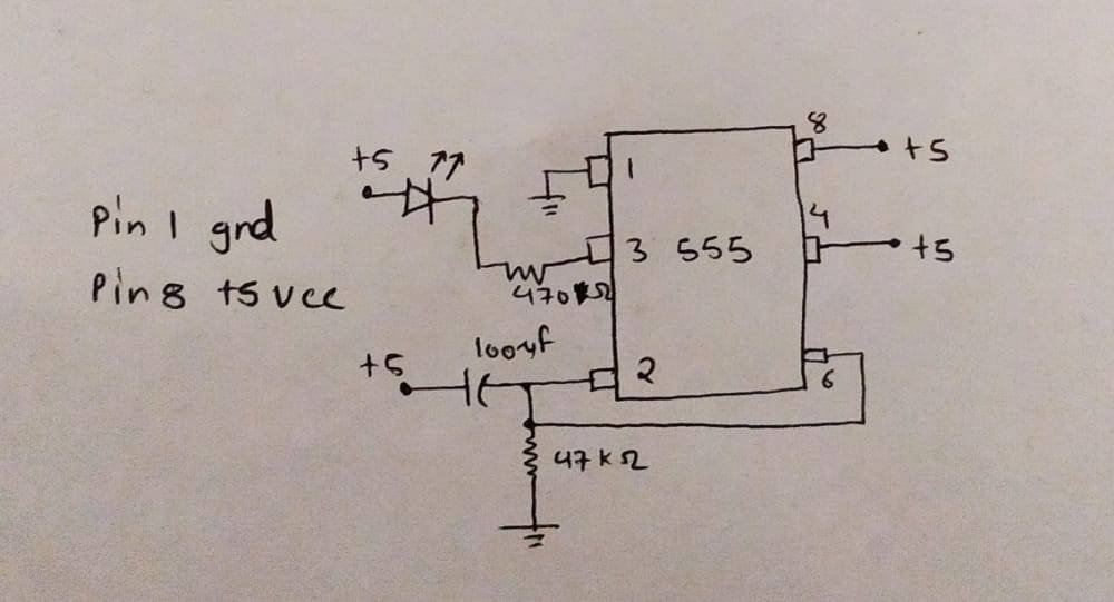

All the connections are the same as the on-timer. The only change is to reverse the polarity of the output LED. Connect the negative leg with the output pin and the positive leg with the positive rail.
Let’s test it
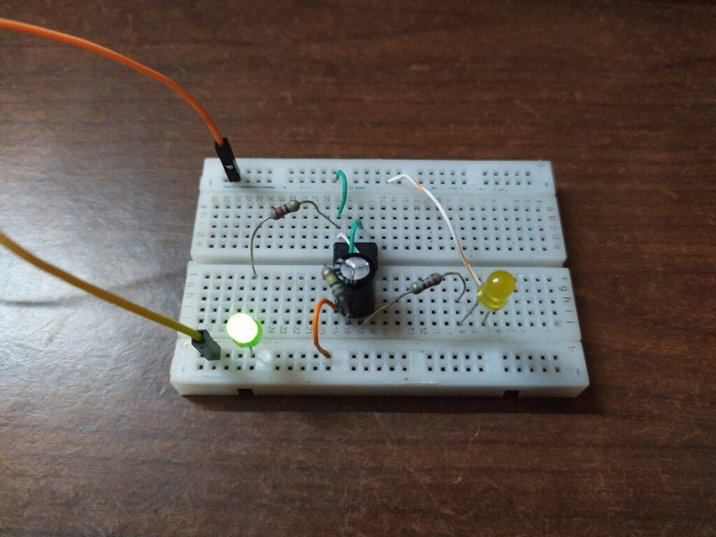
Connect the 9 volts power supply to the circuit and the power LED will turn on. After a delay of few seconds, the second LED will also be turned on/off as per the circuit that you have made. The green LED is for power indication.

Do check out our tutorials on Arduino and Raspberry Pi. We hope that you liked this project and if you have any quarries related to the project then tell us in the comments section below.
HAPPY LEARNING!
Latest 555 timer project
555 Timer LED Flasher | LED Flasher 555 Timer IC
Cell Phone Signal Jammer Using 555 IC | 555 timer project signal jammer
LED Brightness Control using Potentiometer| LED Fade | 555 timer project