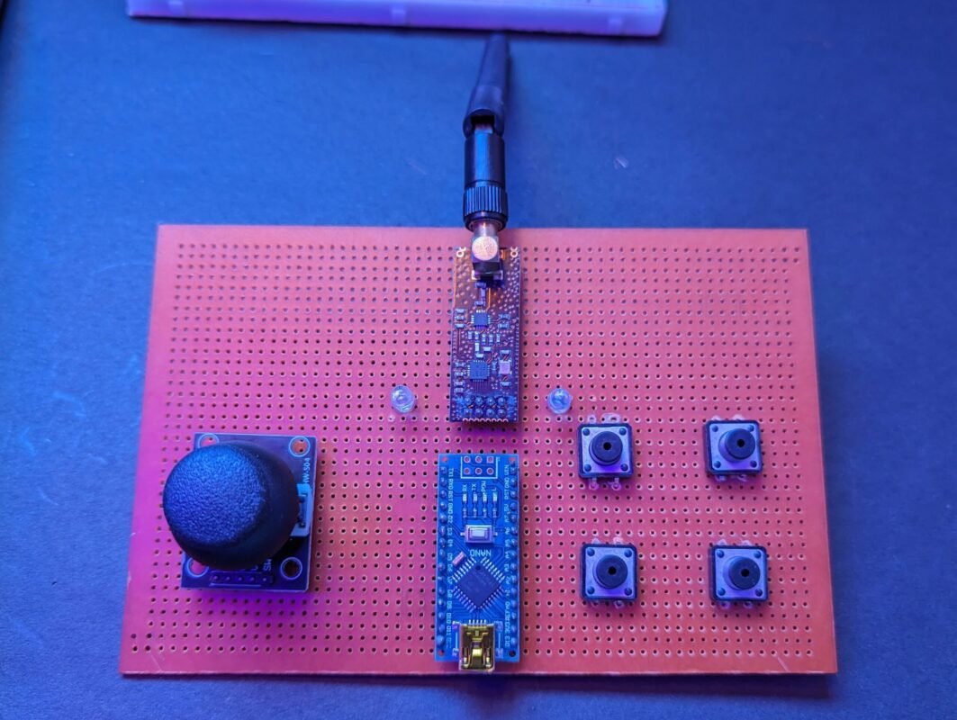
Hey geeks welcome back to the techatronic. This time we have made this great project which is NRF Remote control for Rc car. This remote control can control any of the cars. there is one more device which need to be install in the car or the other device which will control by the remote. the remote control have one transceiver and one controller which manage the remote.
Introduction
This RC remote control is made by the NRF24L01 module which is responsible for wireless communication which you can see in the images. This remote will be paired with the receiver device automatically. and when you press any key or joystick module it will send the information. Previously we made a gesture control robot where we have use the Bluetooth hc-05 master slave communication system. thee master module send the information through the Bluetooth module. the same process uses in this project. but using the NRF module.
The range of the communication of the module is great nearly 100 meters. that is the only reason to use this nrf module in this NRF 24L01 Remote Control for RC Car. All the information will bee provided here how to interface nrf with Arduino, coding and circuit. to make this great project by yourself you need to follow the given instructions.
Here is the list of part’s we are using.
Components Required:-
- NRF24L01 with antenna
- Arduino nano
- Joystick module
- Zero PCB
- push button
- wires
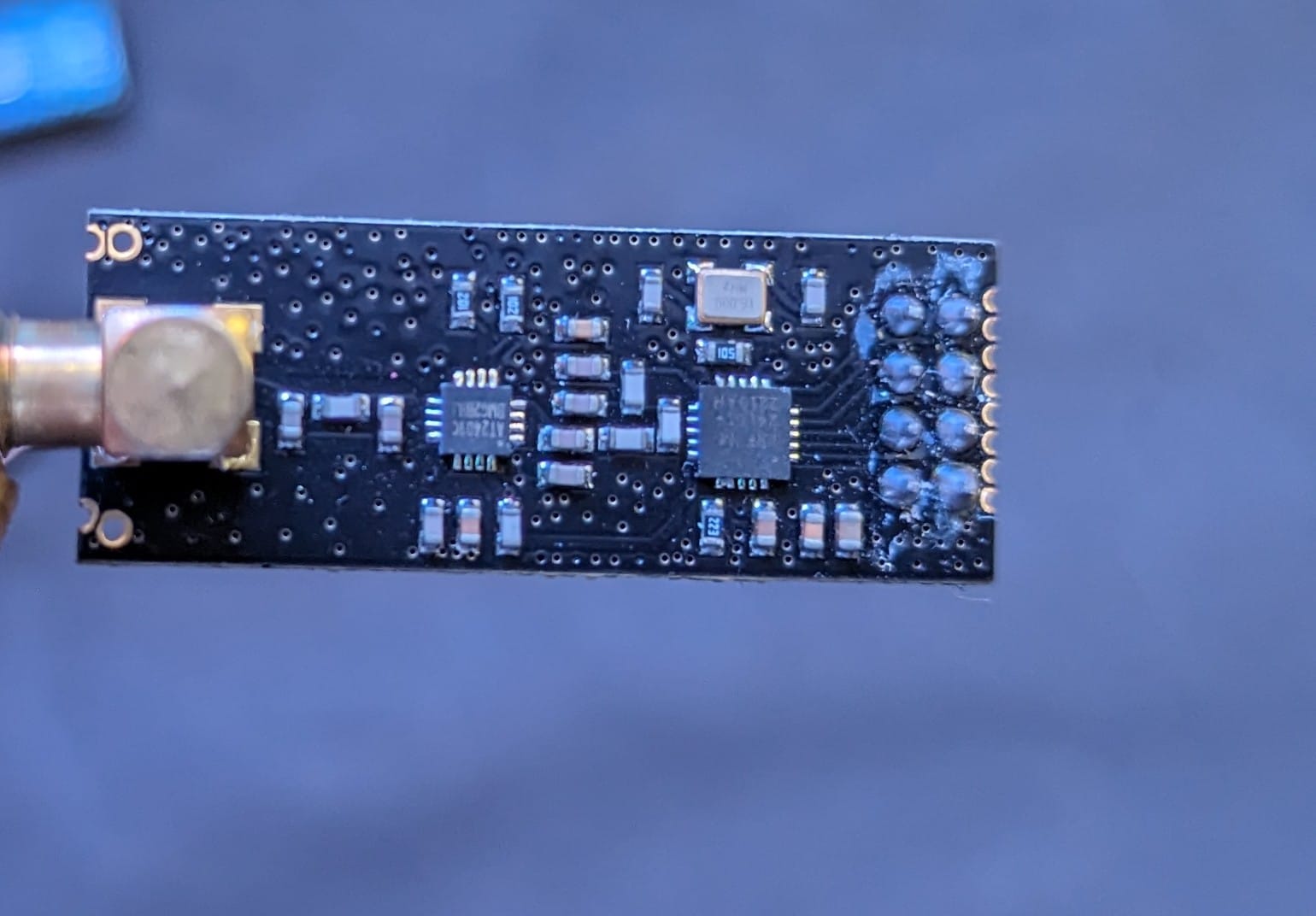
NRF24L01 module is a long-range wireless communication module.This nrf module can use 125 different channels which can help to connect the 125 module connect to each other. and from this 125 channels the each channel can have their own 6 unit to communicate.
Also, the power consubtiom of this module is very low. the nrf24l01 module work only on the 10 mA during the transmission. which is very less even power consumption of led is higher than that.
This module sometimes burn when people make the connection due to the required low voltage. it need maximum 3.3v to operate. if you give extra then it will burn. and the main things is there is no indicator led or nothing to see is it working or not. We are using this module in our NRF remote control system for better communication and low power consumption.
The module have spi pins to communicate with the controllers. MOSI, MISO, SCK , CE, CSN. connect this spi pins to the same spi pins of the arduino or the controller which you are using.
The nrf module available in two different types one is normal NRF24LO1 module and other one with the Long range antenna which enable the communication through the 500 meter. this variation shown here, in addition to the duck antenna, it has a RFX2401C chip which includes PA (Power Amplifier) and LNA (Low-Noise Amplifier).
We need to connect this module to. the arduino nano which transmit the data to the transmitter to receiver.
Joystick module we have interfaced before with the arduino and here is the link you can get all thee information on it here.
Now we need the Circuit diagram. to complete our project.
NRF Remote Circuit Diagram Transmitter
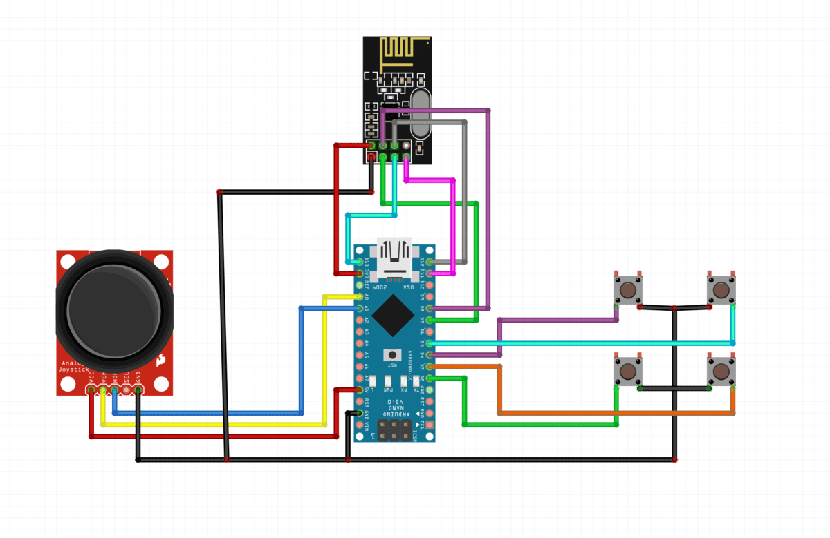
Here you can see the connection clearly in this circuit diagram. joystick verticle and horizontal pin should be connect to the A0 and A1 pins and puch button should connect to the digital input pins. NRF24L01 module connect as required SPI communication.
Connection Table
| Arduino nano | Joystick module | NRF 24L01 | Push Button |
| pin 2 | – | – | PUSH BUTTON1 T1 |
| pin3 | – | – | PUSH BUTTON2 T1 |
| pin4 | – | – | PUSH BUTTON3 T1 |
| pin5 | – | – | PUSH BUTTON4 T1 |
| pin7 | – | CE | – |
| pin8 | – | CSE | – |
| pin11 | – | MOSI | – |
| pin12 | – | MISO | – |
| pin13 | – | SCK | – |
| A0 | V1 | — | – |
| A1 | H1 | – | – |
| VCC | VCC | – | – |
| GND | GND | GND | PB1 T2, PB2 T2, PB3 T3, PB4 T4 |
| 3V3 | – | VCC | – |
NRF Remote control Circuit Diagram Receeiver
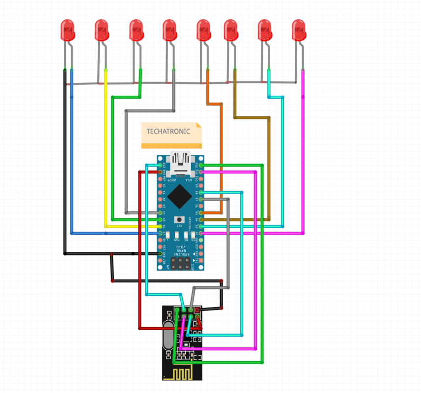
Here the same connection for nrf and arduino and LEDs connect directly to the Arduino nano.
Connection Table
| Arduino nano | LEDs | NRF24L01 |
| A7 | L1 ANODE | – |
| A6 | L2 ANODE | – |
| A5 | L3 ANODE | – |
| A4 | L4 ANODE | – |
| 13 | – | SCK |
| 12 | – | MISO |
| 11 | – | MOSI |
| 8 | – | CSE |
| 7 | CE | |
| 5 | L5 ANODE | – |
| 4 | L6 ANODE | – |
| 3 | L7 ANODE | – |
| 2 | L8 ANODE | – |
| VCC | – | – |
| GND | ALL CATHODE | GND |
| 3V3 | – | VCC |
NRF Remote Control for RC Car code for transmitter
//Library: TMRh20/RF24, https://github.com/tmrh20/RF24/


#include <SPI.h>
#include <nRF24L01.h>
#include <RF24.h>

RF24 radio(7, 8); // CE, CSN

const byte address[6] = "00001";

void setup() {
  Serial.begin(9600);
  radio.begin();
  radio.openWritingPipe(address);
  radio.setPALevel(RF24_PA_MIN);
  radio.stopListening();
  pinMode(2, INPUT_PULLUP);
   pinMode(3, INPUT_PULLUP);
    pinMode(4, INPUT_PULLUP);
     pinMode(5, INPUT_PULLUP);
     pinMode(A0, INPUT_PULLUP);
     pinMode(A1, INPUT_PULLUP);
}

void loop() {

  int m = digitalRead(2);
  int n = digitalRead(3);
  int  o= digitalRead(4);
  int p = digitalRead(5);
  int q = analogRead(A0);
  int r = analogRead(A1);
  Serial.print(m);
  Serial.print("    ");
  Serial.print(n);
  Serial.print("    ");
  Serial.print(o);
  Serial.print("    ");
  Serial.print(p);
  Serial.print("    ");
  Serial.print(q);
  Serial.print("    ");
  Serial.println(r);


  if(m==0)

  {

    const char text[] = "A";
  radio.write(&text, sizeof(text));
  delay(100);

    }

   else if(n==0)

  {

    const char text[] = "B";
  radio.write(&text, sizeof(text));
  delay(100);

    }

    else if(o==0)

  {

    const char text[] = "C";
  radio.write(&text, sizeof(text));
  delay(100);

    }

    else if(p==0)

  {

    const char text[] = "D";
  radio.write(&text, sizeof(text));
  delay(100);

    }


    else if(q>=1000)

  {

    const char text[] = "E";
  radio.write(&text, sizeof(text));
  delay(100);

    }

    else if(q<20)

  {

    const char text[] = "F";
  radio.write(&text, sizeof(text));
  delay(100);

    }

    else if(r<20)

  {

    const char text[] = "G";
  radio.write(&text, sizeof(text));
  delay(100);

    }

else if(r>1000)

  {

    const char text[] = "H";
  radio.write(&text, sizeof(text));
  delay(100);

    }


    else
    {
  const char text[] = "nothing";
  radio.write(&text, sizeof(text));
  delay(100);
}
}
here we using the terms in code which define the following like
#include <SPI.h>
#include <nRF24L01.h>
#include <RF24.h>
Here we are including the nrf libraries into the front end code from backend.
RF24 radio(7, 8); // CE, CSN

const byte address[6] = "00001";
First line define the pins we are using for ce and ece pin of NRF module.
and the second line define the address of the nrf to communicate with the other nrf module
Serial.begin(9600);
  radio.begin();
  radio.openWritingPipe(address);
  radio.setPALevel(RF24_PA_MIN);
  radio.stopListening();
First line start the serial communications between the arduino and the computer which usually uses for seeing the data in serial monitor.
the second line starting the radio communication between the two nrf module.
third line after getting started the the data will be write in thee same frequency so the receiver can receive the same.
pinMode(2, INPUT_PULLUP);
   pinMode(3, INPUT_PULLUP);
    pinMode(4, INPUT_PULLUP);
     pinMode(5, INPUT_PULLUP);
     pinMode(A0, INPUT_PULLUP);
     pinMode(A1, INPUT_PULLUP);
These all lines of codes configuring the input pins which will be used by joystick and push buttons.
 if(m==0)

  {

    const char text[] = "A";
  radio.write(&text, sizeof(text));
  delay(100);

    }
there we are using some conditions like if any button press then what will bee send from transmitter to receiver.
NRF Remote Control for RC Car code for Receiver
#include <SPI.h>
#include <nRF24L01.h>
#include <RF24.h>

RF24 radio(7, 8); // CE, CSN

const byte address[6] = "00001";

void setup() {
  Serial.begin(9600);
  radio.begin();
  radio.openReadingPipe(0, address);
  radio.setPALevel(RF24_PA_MIN);
  radio.startListening();
  pinMode(2, OUTPUT);
   pinMode(3, OUTPUT);
    pinMode(4, OUTPUT);
     pinMode(5, OUTPUT);
     pinMode(A3, OUTPUT);
     pinMode(A2, OUTPUT);
     pinMode(A5, OUTPUT);
     pinMode(A4, OUTPUT);
}

void loop() {

  if (radio.available()) {
    char text[32] = "";
    radio.read(&text, sizeof(text));
    Serial.println(text);


if(strcmp(text,"E")==0)


{

  digitalWrite(2, HIGH);
  digitalWrite(3, LOW);
  digitalWrite(4, HIGH);
  digitalWrite(5, LOW);

}


else if(strcmp(text,"F")==0)

{
  digitalWrite(2, LOW);
  digitalWrite(3, HIGH);
  digitalWrite(4, LOW);
  digitalWrite(5, HIGH);
}


else if(strcmp(text,"H")==0)

{
  digitalWrite(2, LOW);
  digitalWrite(3, HIGH);
  digitalWrite(4, HIGH);
  digitalWrite(5, LOW);

}


else if(strcmp(text,"G")==0)

{
  digitalWrite(2, HIGH);
  digitalWrite(3, LOW);
  digitalWrite(4, LOW);
  digitalWrite(5, HIGH);

}


else
{
  digitalWrite(2, LOW);
  digitalWrite(3, LOW);
  digitalWrite(4, LOW);
  digitalWrite(5, LOW);
}


  }

}
After uploading the both code try to plug the power and observe on thee serial monitor.
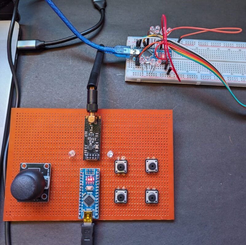
Here you can see both the circuit.
PCBWay PCB Prototyping Services
I have assembled the whole circuit on a breadboard. As you know breadboard assembly is not effective for this type of project. So, PCBWay offers Rapid PCB Prototyping for Your Research Work. I personally, recommend PCBWay because you can get your first-try boards right in 24 hours!

The prototyping stage is the most critical period of time for engineers, students, and hobbyists. PCBWay not only makes your boards quick but also makes your job right as well as cost-effective. This greatly reduces your cost and shortens the time for developing your electronic
PCBWay can provide 2 Layer PCBs to highly advanced HDI and flex boards. Even though the PCBs they produce differ a lot regarding functionality and areas of use. I am impressed with the quality of the boards, the delivery time, and the cost-effectiveness
NRF 24L01 Remote Control working
When we plug both the circuit the transmitter and the receiver connect automatically to each other and start communicating transmitter continuously sends the data to the receiver. and the receiver compares that data with the condition if the condition true or not. in this NRF 24L01 Remote Control for RC Car only we need some basic components.

I don’t have two nano cables so what should I do