
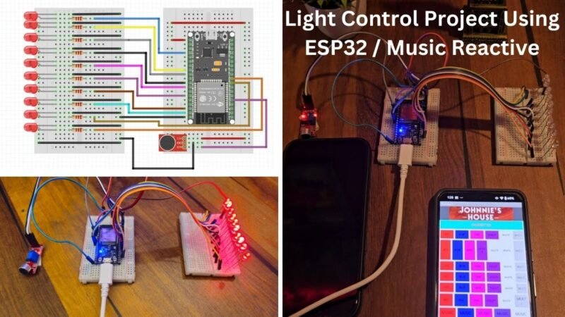
Hey, Welcome back to the Techatronic. Today we are making a very good and interesting Light Control Project Using ESP32. We are making a project which will be control by the Smartphone. There is an application which will connect to the Project device and the device will work according to the mode selected in the application. the application is available for Android device till the date.
ESP32 is the main component in this project. we are using the Bluetooth function of this module. which will connect to the android application. First we need intilize the Bluetooth of esp32. them it will appear in the phones as esp32. Then we will code the LEDs which are connected to the esp32. We need to make many different pattern in the led. each pattern will be close in different case condition. each case associated to the different Character such as A,B,C,D,etc.
For example, if you press A then it will select the 1st pattern programming.if you press B then it will select the pattern B. Esp32 module have the inbuilt wifi and Bluetooth. So we are using the Bluetooth here. This activity is very interesting you can use this project at many places like your working place, your studio. mainly this can be use in the bar and club. where the light effect needed.
Here, we are going to share all the information about the project like , circuit , code and step by step instruction. also we will provide all the software required to make this awesome project. We need a android application to operate this system. so, we will made one application on the Mit app inventor.
To make this project we required some hardware as well as the software.
Components Required for Light Control Project Using ESP32:-
| ESP32S Development Board | BUY LINK |
| Sound sensor | BUY LINK |
| Jumper wire | BUY LINK |
| LEDs | BUY LINK |
| Breadboard | BUY LINK |
| ESP cable | BUY LINK |
ESP32S
ESP32S development Board is very powerful board for tinkerer. who do experiment and invention this board is for them. The esp32s board having 38 GPIO and multipurpose pins which gives us many function like IoT, Bluetooth integration , wifi integration, input output GPIO, Serial communication, I2C Protocol, SPI protocol and many others too. so, if we have any of the above application we can use this board.
The esp32s board having 80MHZ frequency which very high for a microcontroller. It is a low power module which help us to create our desire project using coding. So, we have made a lot of projects on ESP32S the link is given below.
Light Bulb Control using IoT | ESP32 IoT Control
Esp32 Cam Live video Streaming on web
ESP32 with WS2812 Pixel Led Programming
ESP32 with RFID RC522 Module | ESP32 RFID Tutorial #3
These are some example of the esp32s. It is compatible with all of the IoT platform like blynk , MQTT, KME smart and many more.
If you want to use ESP32s module and want to setup esp32 in Arduino Ide you are at te right place.
Sound Sensor
Sound Sensor we are using here it is very simple sound sensor which are having 4 pins. Vcc , ground , D0, A0. we will use the A0 pin in this projects. because in our application there we need the analog data. we are sensing the music here so the music is always in the analog form. the sensor gives the analog output from the A0 to the esp32. ESP32 Process the signal and give output according to the code and music signal.
There are two mode of music Reactive light in this project. in 1st mode the Light will turn on whenever it got the beat and other time the light remain off. and in 2nd mode of music reactive light the number of lights will be directly proportional to the intensity of music beat. SO, all these things are working as Light Control Project Using ESP32.
These are the Compoenents we required to make this project. Now lets talk about the Software we will required. we required 3 software here. 2 IDE software and 1 is for controlling the esp32. Here we need to make the android application using it app inventor.
- Arduino IDE
Arduino Ide is used to program many controller like Arduino , esp. Also, we use this Application to code esp32 module. but this software need to configuration to use with the ESP32. there is a lot of Boards, libraries and functions need to add to this software if you want to code ESP32S with Arduino and we have given how to setup esp32 with Arduino on our website. you can check there every thing. still if you have any query you can ask us in the comment section.
2. Mit App Inventor
In MIT App inventor we need to make the application which will be used to control the ESP Bluetooth. MIT app inventor is a web based application always required to make the android application. So here we need to know each and every step to make the application. First you need to open the MIT app inventor official website.
Step 1
Once the website is opened signup into the website.
After Signup into the website click on the create app.

step 2.
Click on the start new project and give a name to your project.
there will be a dashboard to make the application.
from the left side in the layout section drag and drop the horizontal arrangement on the mobile screen.

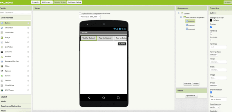
step 3.
now from the right side click on the width and select the fill parent. and go to the user interface Edgar and drop the button to the mobile screen inside the horizontal arrangement. drag and drop the 3 button at least there

Step 4.
now from the right sidebar changes button properties like color, name, and whatever you want.
drag and drop the Bluetoothclient 1 from the connectivity to the mobile screen
Step 5.
Click on the block button on the upper right side. and start the coding
make these two different blocks from control, list picker 1 and Bluetooth.

Step 6.
make 3 more blocks as given in the image from control, bluetoothclient1 and text.

Added more button if you required.

now your app is ready again click on the design button and click on the built and click on the android app there will be a QR code shown by the website. It will be an important part of your control RGB with Arduino project.
Or if you want to download the app you can download.
download mit app inventor on your mobile phone from the google play store and scan the same QR code and it will download the app automatically on your mobile phone.
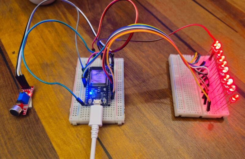
now we will start the second process of making this project.
Creating the circuit which is very easy.
Now. We need a Circuit Diagram to create our project.
Light Control Project Using ESP32 Circuit Diagram

- Connect LED 1 +ve terminal to the ESP32S PIN15
- Connect LED 2 +ve terminal to the ESP32S PIN16
- Connect LED 3 +ve terminal to the ESP32S PIN17
- Connect LED 4 +ve terminal to the ESP32S PIN18
- Connect LED 5 +ve terminal to the ESP32S PIN19
- Connect LED 6 +ve terminal to the ESP32S PIN21
- Connect LED 7 +ve terminal to the ESP32S PIN22
- Connect LED 8 +ve terminal to the ESP32S PIN23
- Connect LED 9 +ve terminal to the ESP32S PIN25
- Connect LED 10 +ve terminal to the ESP32S PIN26
- Connect LED All -ve terminal to the ESP32S Ground pin
- Connect VCC, GND pin of sound sensor to the ESP 5v and gnd pins respectively.
- Connect Sound sensor A0 pin to the A6 pin of ESP32S.
Make sure all the connection should be right and tight
Make sure power supply turn off during the connection
Now we needed to code the ESP32S.
Light Control Project Using ESP32 Code
Here is the code for Light Control Project Using ESP32. which is very simple.
#include "BluetoothSerial.h"

/* Check if Bluetooth configurations are enabled in the SDK */
/* If not, then you have to recompile the SDK */
#if !defined(CONFIG_BT_ENABLED) || !defined(CONFIG_BLUEDROID_ENABLED)
#error Bluetooth is not enabled! Please run `make menuconfig` to and enable it
#endif

BluetoothSerial SerialBT;


void setup() {
  // put your setup code here, to run once:
pinMode(A6, INPUT_PULLUP);

pinMode(15, OUTPUT);
pinMode(16, OUTPUT);
pinMode(17, OUTPUT);
pinMode(18, OUTPUT);
pinMode(19, OUTPUT);
pinMode(21, OUTPUT);
pinMode(22, OUTPUT);
pinMode(23, OUTPUT);
pinMode(25, OUTPUT);
pinMode(26, OUTPUT);

digitalWrite(15, LOW);
digitalWrite(16, LOW);
digitalWrite(17, LOW);
digitalWrite(18, LOW);
digitalWrite(19, LOW);
digitalWrite(21, LOW);
digitalWrite(22, LOW);
digitalWrite(23, LOW);
digitalWrite(25, LOW);
digitalWrite(26, LOW);
delay(100);
digitalWrite(15, HIGH);
digitalWrite(16, HIGH);
digitalWrite(17, HIGH);
digitalWrite(18, HIGH);
digitalWrite(19, HIGH);
digitalWrite(21, HIGH);
digitalWrite(22, HIGH);
digitalWrite(23, HIGH);
digitalWrite(25, HIGH);
digitalWrite(26, HIGH);
delay(30);

delay(400);
Serial.begin(115200);
SerialBT.begin();
}

void loop() {


    if (SerialBT.available()>0)
  {
char m = SerialBT.read();

    Serial.println(m);


switch (m)

{


case 'A': //BLINK

while(1)


{


  // put your main code here, to run repeatedly:
int music = analogRead(A6);
//int pot = analogRead(A7);
//int intensity = map(pot, 0 , 4095 , 0, 1500);
 Serial.println(music);
  Serial.print("      ");
// Serial.println(intensity);
 // delay(50);


if(SerialBT.available()>0)
{
break; }


if( music >= 135 && music <= 185)

{

  digitalWrite(15, LOW);
digitalWrite(16, LOW);
digitalWrite(17, LOW);
digitalWrite(18, LOW);
digitalWrite(19, LOW);
digitalWrite(21, LOW);
digitalWrite(22, LOW);
digitalWrite(23, LOW);
digitalWrite(25, LOW);
digitalWrite(26, LOW);
delay(40);

  }


else
{


  digitalWrite(15, HIGH);
digitalWrite(16, HIGH);
digitalWrite(17, HIGH);
digitalWrite(18, HIGH);
digitalWrite(19, HIGH);
digitalWrite(21, HIGH);
digitalWrite(22, HIGH);
digitalWrite(23, HIGH);
digitalWrite(25, HIGH);
digitalWrite(26, HIGH);

delay(80);


  }


 }

/////
case 'B': //BLINK

while(1)


{
int m = analogRead(A6);
//Serial.println(m);

//if(m>=530 && m<= 545)


int z = -(m-160);

int c = map(z, 0 , 50, 1, 10);
Serial.println(c);

if(c==3)
{
  digitalWrite(15, LOW);
digitalWrite(16, LOW);
digitalWrite(17, LOW);
digitalWrite(18, LOW);
digitalWrite(19, LOW);
digitalWrite(21, LOW);
digitalWrite(22, LOW);
digitalWrite(23, LOW);
digitalWrite(25, LOW);
digitalWrite(26, LOW);

delay(10);
  digitalWrite(15, HIGH);

delay(50);
}


else if(c==4)
{
  digitalWrite(15, LOW);
digitalWrite(16, LOW);
digitalWrite(17, LOW);
digitalWrite(18, LOW);
digitalWrite(19, LOW);
digitalWrite(21, LOW);
digitalWrite(22, LOW);
digitalWrite(23, LOW);
digitalWrite(25, LOW);
digitalWrite(26, LOW);

delay(10);
  digitalWrite(15, HIGH);
digitalWrite(16, HIGH);
delay(50);
}

if(SerialBT.available()>0)
{
break; }


else if(c==5)
{
  digitalWrite(15, LOW);
digitalWrite(16, LOW);
digitalWrite(17, LOW);
digitalWrite(18, LOW);
digitalWrite(19, LOW);
digitalWrite(21, LOW);
digitalWrite(22, LOW);
digitalWrite(23, LOW);
digitalWrite(25, LOW);
digitalWrite(26, LOW);

delay(10);
  digitalWrite(15, HIGH);
digitalWrite(16, HIGH);
digitalWrite(17, HIGH);
delay(50);

}

else if(c==6)
{
 digitalWrite(15, LOW);
digitalWrite(16, LOW);
digitalWrite(17, LOW);
digitalWrite(18, LOW);
digitalWrite(19, LOW);
digitalWrite(21, LOW);
digitalWrite(22, LOW);
digitalWrite(23, LOW);
digitalWrite(25, LOW);
digitalWrite(26, LOW);

delay(10);
  digitalWrite(15, HIGH);
digitalWrite(16, HIGH);
digitalWrite(17, HIGH);
digitalWrite(18, HIGH);
delay(50);
}
if(SerialBT.available()>0)
{
break; }
//Musical LED VU Meter using Arduino Uno
else if(c==7)
{
  digitalWrite(15, LOW);
digitalWrite(16, LOW);
digitalWrite(17, LOW);
digitalWrite(18, LOW);
digitalWrite(19, LOW);
digitalWrite(21, LOW);
digitalWrite(22, LOW);
digitalWrite(23, LOW);
digitalWrite(25, LOW);
digitalWrite(26, LOW);

delay(10);
  digitalWrite(15, HIGH);
digitalWrite(16, HIGH);
digitalWrite(17, HIGH);
digitalWrite(18, HIGH);
digitalWrite(19, HIGH);
delay(50);
}

else if(c==8)
{
  digitalWrite(15, LOW);
digitalWrite(16, LOW);
digitalWrite(17, LOW);
digitalWrite(18, LOW);
digitalWrite(19, LOW);
digitalWrite(21, LOW);
digitalWrite(22, LOW);
digitalWrite(23, LOW);
digitalWrite(25, LOW);
digitalWrite(26, LOW);

delay(10);
  digitalWrite(15, HIGH);
digitalWrite(16, HIGH);
digitalWrite(17, HIGH);
digitalWrite(18, HIGH);
digitalWrite(19, HIGH);
digitalWrite(21, HIGH);
delay(50);
}

if(SerialBT.available()>0)
{
break; }

else if(c==9)
{
  digitalWrite(15, LOW);
digitalWrite(16, LOW);
digitalWrite(17, LOW);
digitalWrite(18, LOW);
digitalWrite(19, LOW);
digitalWrite(21, LOW);
digitalWrite(22, LOW);
digitalWrite(23, LOW);
digitalWrite(25, LOW);
digitalWrite(26, LOW);
delay(10);
  digitalWrite(22, HIGH);
digitalWrite(15, HIGH);
digitalWrite(16, HIGH);
digitalWrite(17, HIGH);
digitalWrite(18, HIGH);
digitalWrite(19, HIGH);
digitalWrite(21, HIGH);
delay(50);
}
if(SerialBT.available()>0)
{
break; }
else if(c==10)
{
  digitalWrite(15, LOW);
digitalWrite(16, LOW);
digitalWrite(17, LOW);
digitalWrite(18, LOW);
digitalWrite(19, LOW);
digitalWrite(21, LOW);
digitalWrite(22, LOW);
digitalWrite(23, LOW);
digitalWrite(25, LOW);
digitalWrite(26, LOW);

delay(10);
  digitalWrite(15, HIGH);
digitalWrite(16, HIGH);
digitalWrite(17, HIGH);
digitalWrite(18, HIGH);
digitalWrite(19, HIGH);
digitalWrite(21, HIGH);
digitalWrite(22, HIGH);
digitalWrite(23, HIGH);
delay(50);
}
else if(c==11)
{
  digitalWrite(15, LOW);
digitalWrite(16, LOW);
digitalWrite(17, LOW);
digitalWrite(18, LOW);
digitalWrite(19, LOW);
digitalWrite(21, LOW);
digitalWrite(22, LOW);
digitalWrite(23, LOW);
digitalWrite(25, LOW);
digitalWrite(26, LOW);

delay(10);
  digitalWrite(15, HIGH);
digitalWrite(16, HIGH);
digitalWrite(17, HIGH);
digitalWrite(18, HIGH);
digitalWrite(19, HIGH);
digitalWrite(21, HIGH);
digitalWrite(22, HIGH);
digitalWrite(23, HIGH);
digitalWrite(25, HIGH);
delay(50);
}
if(SerialBT.available()>0)
{
break; }
else if(c==12)
{
  digitalWrite(15, LOW);
digitalWrite(16, LOW);
digitalWrite(17, LOW);
digitalWrite(18, LOW);
digitalWrite(19, LOW);
digitalWrite(21, LOW);
digitalWrite(22, LOW);
digitalWrite(23, LOW);
digitalWrite(25, LOW);
digitalWrite(26, LOW);

delay(10);
  digitalWrite(15, HIGH);
digitalWrite(16, HIGH);
digitalWrite(17, HIGH);
digitalWrite(18, HIGH);
digitalWrite(19, HIGH);
digitalWrite(21, HIGH);
digitalWrite(22, HIGH);
digitalWrite(23, HIGH);
digitalWrite(25, HIGH);
digitalWrite(26, HIGH);
delay(50);
}
if(SerialBT.available()>0)
{
break; }
else
{

  digitalWrite(15, LOW);
digitalWrite(16, LOW);
digitalWrite(17, LOW);
digitalWrite(18, LOW);
digitalWrite(19, LOW);
digitalWrite(21, LOW);
digitalWrite(22, LOW);
digitalWrite(23, LOW);
digitalWrite(25, LOW);
digitalWrite(26, LOW);

delay(50);
  }


//////


}


case 'C': //BLINK

while(1)


{
if(SerialBT.available()>0)
{
break; }


digitalWrite(15, LOW);
digitalWrite(16, LOW);
digitalWrite(17, LOW);
digitalWrite(18, LOW);
digitalWrite(19, LOW);
digitalWrite(21, LOW);
digitalWrite(22, LOW);
digitalWrite(23, LOW);
digitalWrite(25, LOW);
digitalWrite(26, LOW);

delay(50);
}


case 'D': //BLINK

while(1)


{
if(SerialBT.available()>0)
{
break; }
digitalWrite(15, HIGH);
digitalWrite(16, HIGH);
digitalWrite(17, HIGH);
digitalWrite(18, HIGH);
digitalWrite(19, HIGH);
digitalWrite(21, HIGH);
digitalWrite(22, HIGH);
digitalWrite(23, HIGH);
digitalWrite(25, HIGH);
digitalWrite(26, HIGH);
delay(50);
}


case 'E': //BLINK

while(1)


{


if(SerialBT.available()>0)
{
break; }

digitalWrite(15, LOW);
digitalWrite(16, LOW);
digitalWrite(17, LOW);
digitalWrite(18, LOW);
digitalWrite(19, LOW);
digitalWrite(21, LOW);
digitalWrite(22, LOW);
digitalWrite(23, LOW);
digitalWrite(25, LOW);
digitalWrite(26, LOW);


delay(150);

digitalWrite(15, HIGH);
digitalWrite(16, HIGH);
digitalWrite(17, HIGH);
digitalWrite(18, HIGH);
digitalWrite(19, HIGH);
digitalWrite(21, HIGH);
digitalWrite(22, HIGH);
digitalWrite(23, HIGH);
digitalWrite(25, HIGH);
digitalWrite(26, HIGH);
delay(150);
}


case 'F': //BLINK

while(1)


{

  //int pot = analogRead(A7);
int intensity = 150;

if(SerialBT.available()>0)
{
break; }


digitalWrite(15, HIGH);

delay(intensity);

digitalWrite(15, LOW);

delay(intensity);


digitalWrite(16, HIGH);

delay(intensity);


digitalWrite(16, LOW);

delay(intensity);


digitalWrite(17, HIGH);

delay(intensity);

digitalWrite(17, LOW);

delay(intensity);


digitalWrite(18, HIGH);

delay(intensity);

digitalWrite(18, LOW);

delay(intensity);


digitalWrite(19, HIGH);

delay(intensity);
digitalWrite(19, LOW);

delay(intensity);


digitalWrite(21, HIGH);

delay(intensity);
digitalWrite(21, LOW);

delay(intensity);


digitalWrite(22, HIGH);

delay(intensity);
digitalWrite(22, LOW);

delay(intensity);


digitalWrite(23, HIGH);

delay(intensity);
digitalWrite(23, LOW);

delay(intensity);


digitalWrite(25, HIGH);

delay(intensity);
digitalWrite(25, LOW);

delay(intensity);


digitalWrite(26, HIGH);

delay(intensity);
digitalWrite(26, LOW);

delay(intensity);
}


case 'G': //BLINK

while(1)


{


int intensity = 150;

if(SerialBT.available()>0)
{
break; }


digitalWrite(15, LOW);
digitalWrite(16, LOW);
digitalWrite(17, LOW);
digitalWrite(18, LOW);
digitalWrite(19, LOW);
digitalWrite(21, LOW);
digitalWrite(22, LOW);
digitalWrite(23, LOW);
digitalWrite(25, LOW);
digitalWrite(26, LOW);

delay(intensity);


digitalWrite(15, HIGH);

delay(intensity);

digitalWrite(16, HIGH);

delay(intensity);


digitalWrite(17, HIGH);

delay(intensity);

digitalWrite(18, HIGH);

delay(intensity);
digitalWrite(19, HIGH);

delay(intensity);
digitalWrite(21, HIGH);

delay(intensity);

digitalWrite(22, HIGH);

delay(intensity);


digitalWrite(23, HIGH);

delay(intensity);

digitalWrite(25, HIGH);

delay(intensity);
digitalWrite(26, HIGH);

delay(intensity);


}

////


}

  }
}
After uploading the code into the esp32S. Connect the application to the esp32s.
- Open phone setting > Bluetooth setting> pair new device
- Select the ESP32 device in your available device
- Now go to the app drawer of your phone
- touch and hold on the application icon
- go to the permission and allow for nearby device
- now open the application and click on the connect
- select there the ESP32 device
- Now, you can select the mode and pattern from the application.
If you have any problem in project you can ask us in the comment section.