
Hey guys, hope you are doing good. Are you searching for what a flip flop in digital electronics is? Well if so then you are at the right place because we are going to talk about flip flops in this post. A storage element in digital electronics that can maintain a binary state indefinitely until directed by an input signal to switch states. Storage elements that operate with clock levels are referred to as latches and those controlled by a clock transition are referred to as the flip flop. So in this article, we are going to discuss the types of flip flops in detail. You can also check articles on Arduino and basic electronics.
We are going to make the circuits of these flip flop in digital electronics using some basic gates so if you don’t familiar with the concepts of gates then go through it first.
Table of Contents
SR Flip Flop (Set Reset)

You can see the truth table for SR flip flop in the image given below. The output for the next state (Qn+1) is 0 and 1 (also called hold) for first two cases, 0 and 0 (also called reset) for second two cases, 1 and 1 (also called set) for third two cases, and invalid for last two cases.
Logic circuit for SR flip flop
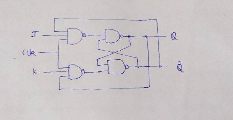
JK Flip Flop

J-K flip flop: You can see the truth table for jk flip flop in the image which is given below. The output for the next state (Qn+1) is 0 and 1 (also called hold) for first two cases, 0 and 0 (also called reset) for second two cases, 1 and 1 (also called set) for third two cases, 1 and 0 (also called toggle) for last two cases.
Logic circuit for JK flip flop
T Flip Flop

T flip flop (toggle): You can find the truth table for the t flip flop in the image given below. The output for the next state (Qn+1) is 0 and 1 ( also called hold) for the first two cases, 1 and 0 (also called toggle) for the next two cases.
Logic circuit for T flip flop
D Flip Flop

D flip flop (data, delay): You can find the truth table for the d flip flop in the image given below. The output for the next state (Qn+1) is 0 and 0 for the first two cases, 1 and 1 for the next two cases.
Logic circuit for D flip flop
If you want to make logic gates circuits using transistor then check out our article on it.
Conclusion
We hope that you understand the types and working of all the flip flop in digital electronics that we have discussed above. If you have any doubts regarding this post then do let us know in the comments section given below. Also, do check out projects on Arduino and Raspberry Pi made by us.
Happy learning!