Hey guys, welcome back to Techatronic. Have you ever seen a current detector 555 timer project used to find the flow of electric current in the wires? Sometimes an electric tester is also used to serve the same purpose but a problem associated it with is that we need to touch its tip with the wire.
Table of Contents
Introduction
It needs physical contact between the tester and the conductor which is sometimes not possible due to the insulation of wires. So in this article, we are going to make an AC/DC current detector circuit using IC 555. Please follow the steps carefully to make your own current detector. if you don’t have basic knowledge of the 555 timer ic we have some articles on what is 555 timer is and much more. you can bookmark our website to learn more.

The detailed work of the project and the circuit diagram is given below. You can also check more projects on basic electronics made by us. Check out our project, clap switch with Arduino and sound sensor.
About the current detector 555 circuit
- The 555 timer IC has a total of 8 pins, 4 pins on one side.
- You can identify the pin number by viewing its datasheet or the notch which is marked on the IC.
- Pin number 1 is ground and 8 is VCC.
- Take a current-carrying wire like a DC adapter and bring it near to the antenna of the current detector circuit that we have made.
- If the current is flowing in the wire then the LED starts blinking and the buzzer starts ringing.
- The blinking of the LED and the buzzer sound indicates that the current is present. It is a non-contact AC/DC current detector 555 circuit.
Components Required
You need the following components and please use them with the correct values as mention below for proper working of the project.
- 555 timer IC
- Breadboard and small pieces of copper wire
- 10-K ohm and 1-k ohm resistors
- 9-volts DC battery
- 1-uF/ 63-volts capacitor
- BC547 transistor
- Buzzer and an LED
- Insulated copper wire
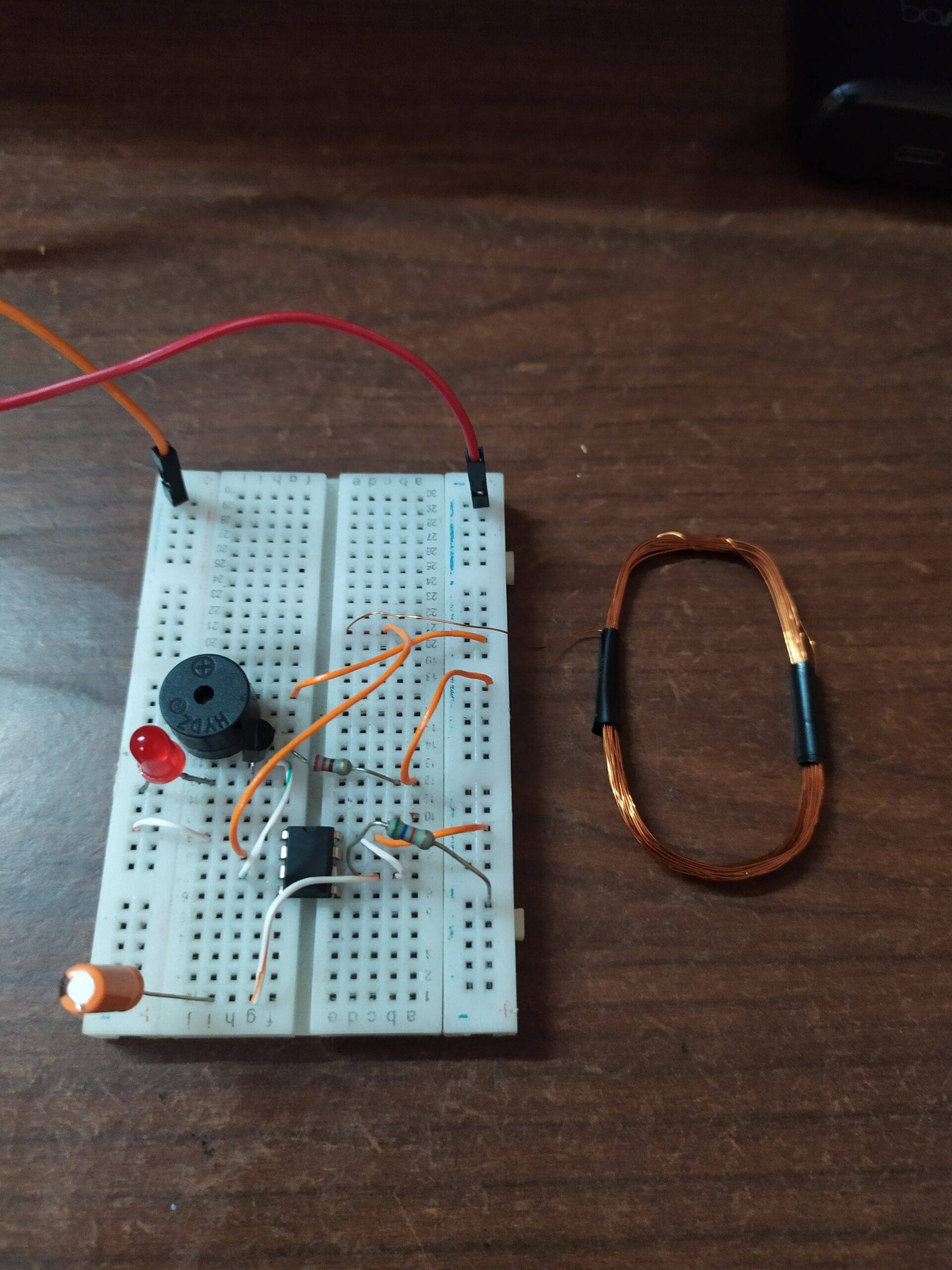
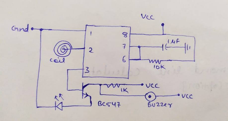
current detector 555 circuit

- Place the 555 timer in the middle of the breadboard and connect pin number 1 to the negative rail and 8 to the positive rail of the breadboard.
- Take a piece of small wire and connect it with pin numbers 6 and 7.
- Attach a 10-k ohm resistor between pin number 6 and the positive rail of the breadboard.
- Connect the negative wire of the capacitor with the negative rail of the breadboard and the positive wire with pin number 7 of the 555 IC.
- Now join the base of the transistor with pin number 3 of the IC. Connect a 1-k ohm resistor between the positive rail and the collector of the transistor.
- Take a buzzer and join its positive leg with the positive rail and negative leg with the collector.
- Attach the negative leg of the LED to the negative rail and the positive leg to the emitter of the transistor.
- Now take a copper wire and make an antenna of it. Connect this with pin number 2 of the IC.
Final Look of the Project
Now your circuit is complete. Connect a 9-volts battery to it so the current detector starts working.
We hope that you understand the project completely. If you are facing any difficulties while making this project then let us know in the comments section below. Also, check out projects based on Arduino and IoT.
Latest 555 timer projects
Railway Signal Using 555 Timer IC | 555 IC project
555 Timer LED Flasher | LED Flasher 555 Timer IC
555 Timer Square Wave Generator | Astable Multivibrator
LED Fade In And Out Circuit Using 555 Timer IC | electronic tutorial
