
Table of Contents
Introduction
Hey folks, hope you are doing fine. In this post, we are going to make a soft start circuit for the motors that are used in the industries. All the details and circuit diagrams along with the components list are given below. You can also read more articles on Arduino and IoT. Just complete the circuit and then connect the power supply to the circuit. So are you excited about making it?

Description
- The motors that are used in industries draw a large amount of current during the initial start so, we need soft start circuit for these motors.
- Sometimes they make large noises and sometimes the fluctuation is too large that can damage the wiring or the other machines.
- So it is necessary for them to start slowly and then after a few seconds, they are back to their normal speed of operation.
- We are making a soft start circuit for the motors. At the output, we get PWM signals (pulse width modulation).
- Initially, the speed of the motor is slow but it can attain its maximum speed in a short interval of time which can be adjusted by rotating the potentiometer.
- You can also check the DC motor speed controller circuit using 555 timer ic made by us.
Components Required
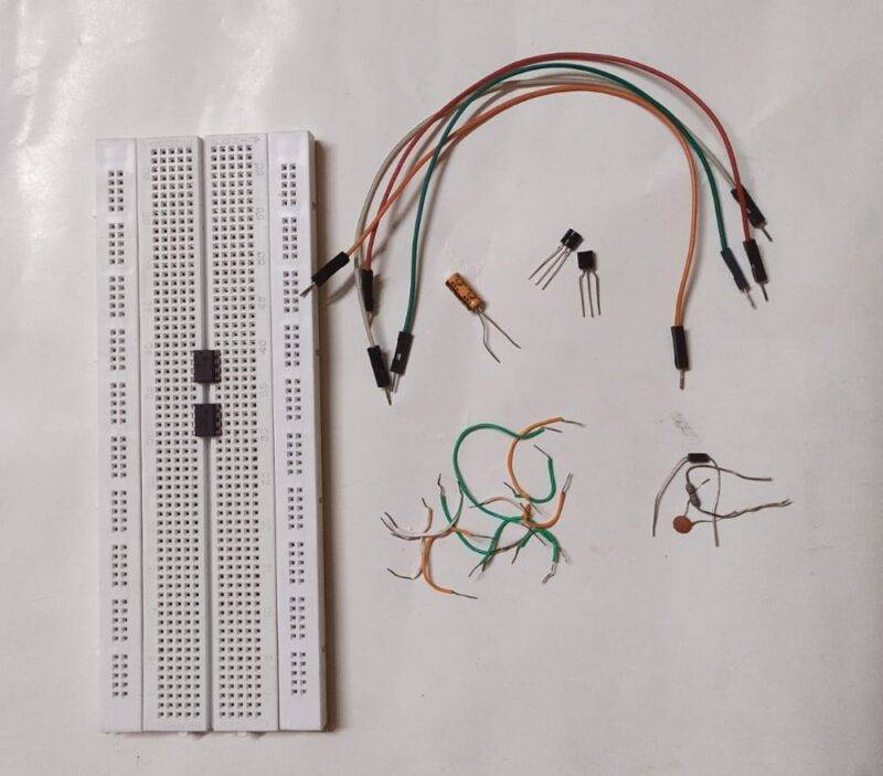
Use components
| Two 555 timer ic | |
| Capacitors 0.01 uF, 0.1 uF, 1 uF, 100 uF | BUY LINK |
| 1n4007 diode | BUY LINK |
| Transistors BC557, BC547 | |
| Connecting wires | BUY LINK |
| breadboard | BUY LINK |
| Resistors 1K, 100K, 100R, 220R, 2.2K | BUY LINK |
| 100K potentiometer | BUY LINK |
| DC motor | BUY LINK |
| 9 volts battery | BUY LINK |
Circuit Diagram
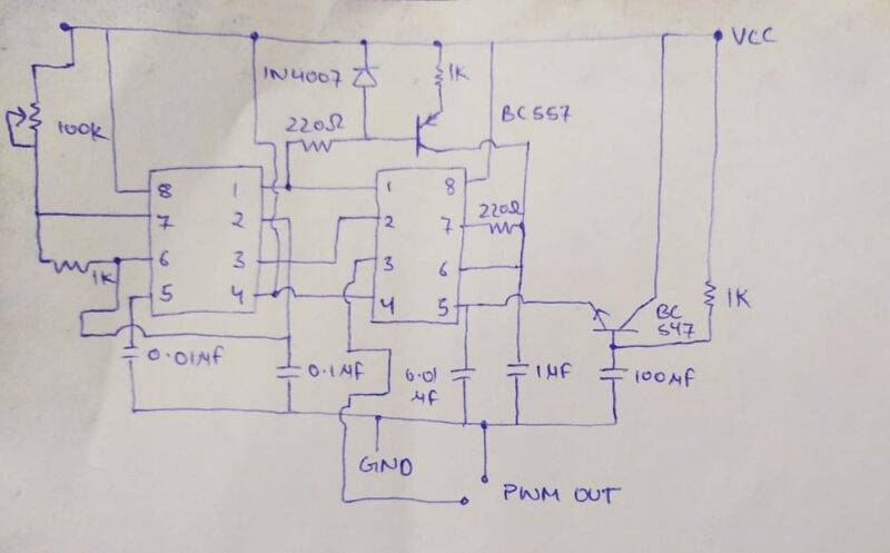
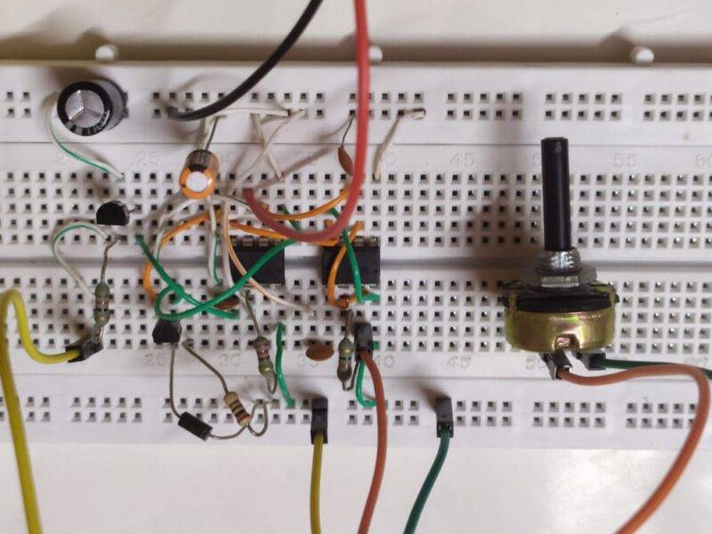
- Take two 555 timer ic’s and place them in the breadboard. Then take a 9 volts battery and connect its positive terminal to the positive rail and negative terminal to the negative rail of the breadboard.
- Connect pin 8 of both the ic’s with positive rail. Join the 0.01 uF capacitor with pin 5 and the negative rail.
- Attach a 100K potentiometer with pin 7 and the positive rail. Join Pins 2 and 6 together. Connect pin 4 of both the ic’s with the positive rail.
- Join pins 1 of both of the ic’s with the negative rail.
- Attach a 0.1 uF capacitor between pin 2 and the negative rail.
- Connect pin 3 of the first 555 timer ic with pin 2 of the second 555 timer ic.
- Now, lets see the connections for the second timer ic. Take a BC547 transistor and connect its emitter pin with pin 5 of the ic and its base pin with the positive leg of a 100 uF capacitor. Join the negative leg of the capacitor with the negative rail.
- Connect the collector pin of the transistor with the positive rail. Join pins 7 and 6 together.
- Attach the base pin of the BC557 transistor with the diode as show in the figure.
- Join the collector pin with pin 7 of the ic.
- Connect the emitter leg of the transistor with the positive rail.
- Make the other connections properly as shown in the diagram.
- You can take the output from pin 3 of the second 555 timer ic and the negative rail.
Let’s Test the Circuit
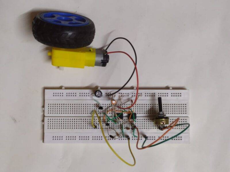
We hope that you liked this project and if you have any doubts regarding it then please feel free to ask them in the comments section given below. Also, do check out more tutorials on Arduino and Raspberry Pi.
Thanks for reading.