Table of Contents
Introduction
Hey Techies. Have you ever seen any seven-segment display in your daily life?
in washing machine timer? in weighing machines, electricity meters, and many more places we see the seven-segment display everywhere.
so, today we are going to teach you what is it and how does it work. here we are going to interface the 7 segment display Arduino.
here Arduino will control the seven-segment and the number inside the seven-segment. this is really interesting and useful.
you can make many things with this seven-segment display in your home even you can make a digital clock for your wall with the seven-segment display.
I will share all the detail about the seven segments & Arduino to make it possible.
So, here a question arises what do we need and how we can make it. so, here you need to know some basics of electronic and Arduino programming.
if you don’t have anything you can visit our website where you can get all the basic detail here. now you do not need to buy the costly item you can make all with the techatronic.
What is 7 segment display?
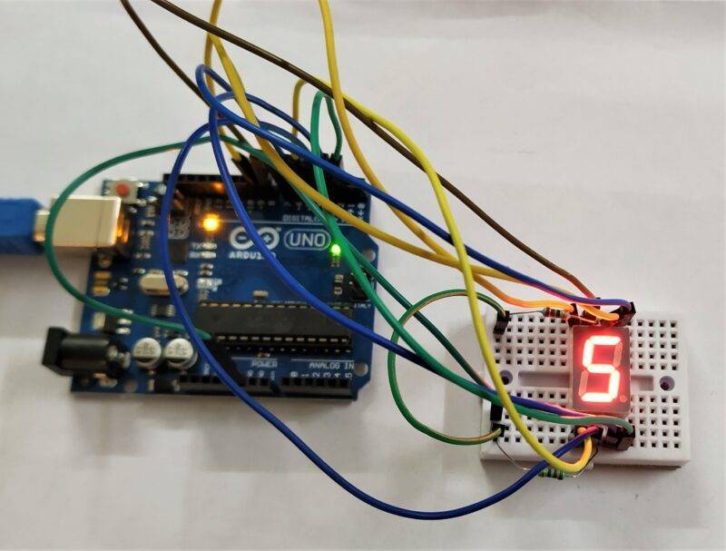
- The seven-segment display uses to display decimal numbers and these are the form of an electronic display device so so the seven-segment display could be an alternative to the available complex dot matrix displays.
- if you need a small display then you can refer to this consume very low power. these displays are widely used in electronic devices like,
electronic meters, basic calculators, digital clocks, and where we need to display numerical information. this 7 segment display is made by 7 leds which is associated with the different pins and when you power any pin the associated led will glow.
- Here we will use programming on 7 segment display Arduino programming to show the number which I want to show. we will make the counter too with the devices.
- There are two types of seven-segment displays one is a common cathode and another is a common anode.
- in the common cathode, you need to connect the negative of battery or power source to the common cathode pin and in the common anode, you need to connect the anode pin of display with the positive terminal of power.
What is Seven segment Arduino activity?
- This is a very interesting activity of Arduino and programming. in this activity,
- we will make a program to run the seven-segment display.
- you need a circuit diagram and code to make this awesome activity so we are going to share the code and circuit here.
- this activity is similar to the print numbers on LCD.
- so here we are print numbers on Seven segment display using Arduino.
we can make do this activity without the Arduino too.
but with the Arduino, there are fewer chances of errors & bugs. honestly, you need to write the code and make the connections. and your activity will be done.
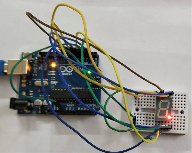
How does it work?/ working
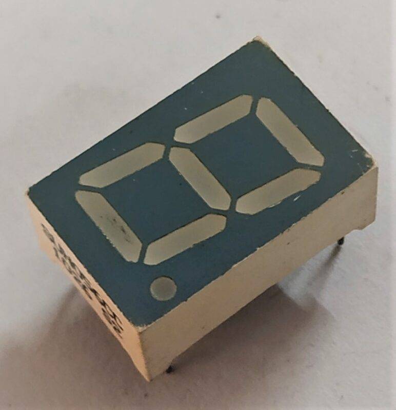
So, here at the seven-segment display 7 led inside the device which associated with the part of the number. f
or example, if you can see at the display if we want to make 1 on the display you there is two led to glow.
if you want to display 2 there 5 led to be a glow to make the 2 number in the display and if you want to display 6 you need to glow 6 led inside the device.
so there is seven led behind the seven segments associated with the seven different pins. and when the logic will high for any pin then the associated led will glow and make some number there.
so, there we will use Arduino output pins to trigger the led pins of the segment display. So, according to our code and the logic, the number makes in the display.
How to make this 7 seven-segment display Arduino Activity?
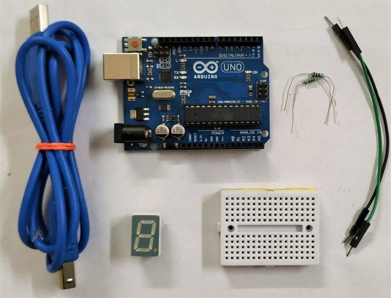
so, there we need some components, Arduino code, and the circuit diagram to make it possible. Here everything is given follow the instructions carefully.
Components Required?
| Arduino Uno | BUY LINK |
| Breadboard | BUY LINK |
| Seven segment | BUY LINK |
| 220-ohm resistor | BUY LINK |
| Jumper wires | BUY LINK |
| Arduino Uno cable | BUY LINK |
7 segment display Arduino circuit
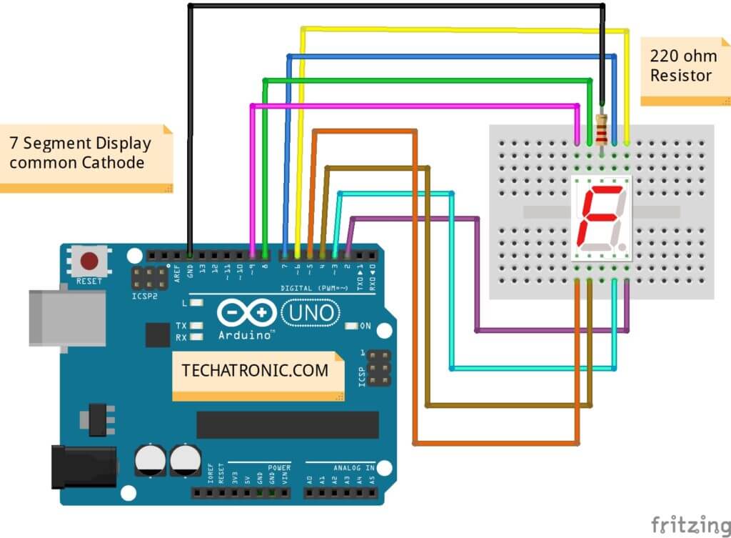
Connection Table
| Arduino UNO | Seven Segment Display | 220 Ohm 2 Resistor |
| 7 Pin | A Pin | |
| 6 Pin | B Pin | |
| 3 Pin | C Pin | |
| 4 Pin | D Pin | |
| 5 Pin | E Pin | |
| 8 Pin | F Pin | |
| 9 Pin | G Pin | |
| 2 Pin | DP Pin | |
| Both Common | Terminal 1 | |
| GND | Terminal 2 |
Arduino seven-segment Code
Make all the given connections carefully. and then upload the given code to the Arduino with the help of Arduino IDE.
Common Cathode Code
 // TECHATRONIC.COM
 void setup()
 {
  pinMode(2, OUTPUT);
  pinMode(3, OUTPUT);
  pinMode(4, OUTPUT);
  pinMode(5, OUTPUT);
  pinMode(6, OUTPUT);
  pinMode(7, OUTPUT);
  pinMode(8, OUTPUT);
  pinMode(9, OUTPUT);
 }
 void loop()
 {
  // ZERO
  digitalWrite(2, LOW);
  digitalWrite(3, HIGH);
  digitalWrite(4, HIGH);
  digitalWrite(5, HIGH);
  digitalWrite(6, HIGH);
  digitalWrite(7, HIGH);
  digitalWrite(8, HIGH);
  digitalWrite(9, LOW);
  delay(2000); // Wait for 2000 millisecond(s)
  // ONE 1
  digitalWrite(2, LOW);
  digitalWrite(3, HIGH);
  digitalWrite(4, LOW);
  digitalWrite(5, LOW);
  digitalWrite(6, HIGH);
  digitalWrite(7, LOW);
  digitalWrite(8, LOW);
  digitalWrite(9, LOW);
  delay(2000); // Wait for 2000 millisecond(s)
   // 2 TWO
  digitalWrite(2, LOW);
  digitalWrite(3, LOW);
  digitalWrite(4, HIGH);
  digitalWrite(5, HIGH);
  digitalWrite(6, HIGH);
  digitalWrite(7, HIGH);
  digitalWrite(8, LOW);
  digitalWrite(9, HIGH);
  delay(2000); // Wait for 2000 millisecond(s)
   // 3 THREE
  digitalWrite(2, LOW);
  digitalWrite(3, HIGH);
  digitalWrite(4, HIGH);
  digitalWrite(5, LOW);
  digitalWrite(6, HIGH);
  digitalWrite(7, HIGH);
  digitalWrite(8, LOW);
  digitalWrite(9, HIGH);
  delay(2000); // Wait for 2000 millisecond(s)
   // 4 FOUR
  digitalWrite(2, LOW);
  digitalWrite(3, HIGH);
  digitalWrite(4, LOW);
  digitalWrite(5, LOW);
  digitalWrite(6, HIGH);
  digitalWrite(7, LOW);
  digitalWrite(8, HIGH);
  digitalWrite(9, HIGH);
  delay(2000); // Wait for 2000 millisecond(s)
   // 5 FIVE
  digitalWrite(2, LOW);
  digitalWrite(3, HIGH);
  digitalWrite(4, HIGH);
  digitalWrite(5, LOW);
  digitalWrite(6, LOW);
  digitalWrite(7, HIGH);
  digitalWrite(8, HIGH);
  digitalWrite(9, HIGH);
  delay(2000); // Wait for 2000 millisecond(s)
   // 6 SIX
  digitalWrite(2, LOW);
  digitalWrite(3, HIGH);
  digitalWrite(4, HIGH);
  digitalWrite(5, HIGH);
  digitalWrite(6, LOW);
  digitalWrite(7, HIGH);
  digitalWrite(8, HIGH);
  digitalWrite(9, HIGH);
  delay(2000); // Wait for 2000 millisecond(s)
   // 7 SEVEN
  digitalWrite(2, LOW);
  digitalWrite(3, HIGH);
  digitalWrite(4, LOW);
  digitalWrite(5, LOW);
  digitalWrite(6, HIGH);
  digitalWrite(7, HIGH);
  digitalWrite(8, LOW);
  digitalWrite(9, LOW);
  delay(2000); // Wait for 2000 millisecond(s)
   // 8 EIGHT
  digitalWrite(2, LOW);
  digitalWrite(3, HIGH);
  digitalWrite(4, HIGH);
  digitalWrite(5, HIGH);
  digitalWrite(6, HIGH);
  digitalWrite(7, HIGH);
  digitalWrite(8, HIGH);
  digitalWrite(9, HIGH);
  delay(2000); // Wait for 2000 millisecond(s)
   // 9 NINE
  digitalWrite(2, LOW);
  digitalWrite(3, HIGH);
  digitalWrite(4, HIGH);
  digitalWrite(5, LOW);
  digitalWrite(6, HIGH);
  digitalWrite(7, HIGH);
  digitalWrite(8, HIGH);
  digitalWrite(9, HIGH);
  delay(2000); // Wait for 2000 millisecond(s)
   // . DOT
  digitalWrite(2, HIGH);
  digitalWrite(3, LOW);
  digitalWrite(4, LOW);
  digitalWrite(5, LOW);
  digitalWrite(6, LOW);
  digitalWrite(7, LOW);
  digitalWrite(8, LOW);
  digitalWrite(9, LOW);
  delay(2000); // Wait for 2000 millisecond(s)
 }
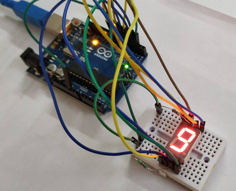
Upload the given Code to the Arduino and if you have any problem uploading the code visit our Arduino software tutorial.


