
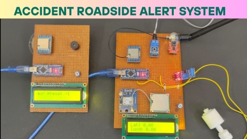
He guys welcome back again, this time we have made a very useful project which can help in daily life problems. So the project is accident roadside alert system with car breakdown alarm as the name suggest this is the system which can alert any accident occur on the roadside also there is some system which can detect the car breakdown. So we know every year there is a lot of accident occur on the road due to the many reasons try to find out the sum of the reasons which can prevent the accident.
Table of Contents
Introduction
In this project we will inspects some measures in car which can prevent the car breakdown so the car breakdown is also a reason of accident for example if there is a sudden breakdown car like if the tyre of vehicle suddenly punctured then there is a chance of accident. So we will measure the given aspects of the vehicle and which can decided the car breakdown and went to help and where to help.
In this accident roadside alert system we will measure.
Air pressure of tyre
Battery voltage of battery
Fuel Indication by fuel level sensor
Accident detection by vibration sensor
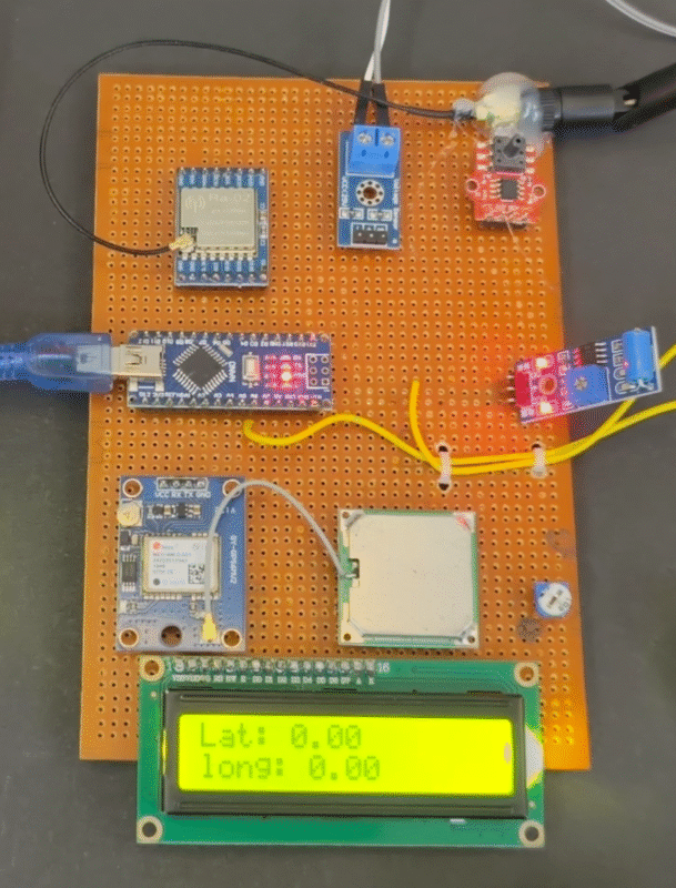
There will be two part in this project first in transmitter and other is receiver so as we said there is two part transmitter and receiver so there will be a wireless communication between both of them. So here where using Lora communication. In which we have placed air pressure sensor battery voltage sensor and accident Detection sensor and fuel level sensor.
I mean vibration sensor. GPS module can give us the location in the form of latitude and longitude so all these component has been deployed In the transmitter part. And we will collect all these data into the transmitter like a pressure from the tire and battery voltage and vibration sensor output and GPS module data all these data will be transferred by the Lora communication.
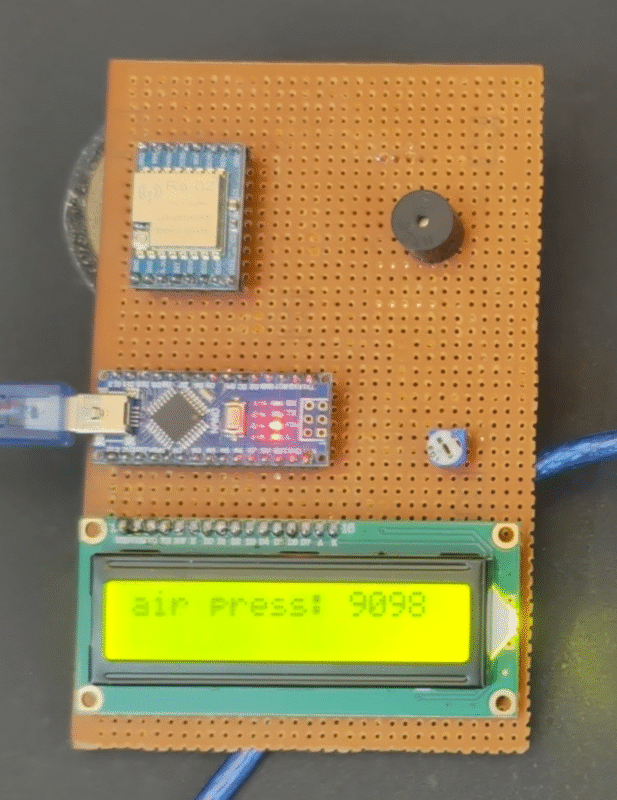
So , here we are getting data from the Lora receiver and display all the data on to a 16 x2 LCD display. Also there is N ESP connected with this receiver part which is transmitted this data to the cloud server. And from the cloud server these data will be transmit to our smartphone Buy using link application. So in this project where using blink iot cloud application to receive the longitude and latitude and other data.
Also we have installed a buzzer into the receiver. This buzzer start beeping when the car has reached to The breakdown position. So hear the question is what is breakdown position. As always knows there were using a sensor name a pressure sensor which are using hair in this project to measure the tyre air pressure. If the tire air pressure is less than it will notify us by the notification of breakdown condition.
Other condition is battery voltage where using a voltage sensor here which continuously measure the voltage from the battery. So the battery voltage is less than the throshed threshold voltage then it will notify us The breakdown condition. Here we are using a fuel level sensor which are continuously checking the fuel inside the vehicle it is enough or not so if there is not in a fuel it will start sending the data and it undergoes into the. breakdowb condition. So this are the breakdown conditions of any vehicle which we are checking with this Accident Roadside Alert system project.
If any breakdown condition occurs then the transmitter transmit the data to the receiver and we have deployed a buzzer in the receiver which start beeping and displaying on the display from nearby. The receiver part will be applied at the reason near to the highway so car will transmit the data from their transmitter to receiver and person near the receiver at the Helping Centre can talk to you and getting your location from the receiver part. Also the mobile or this system will get the notification from the blink cloud server.
So this project is very good and very simple to make we are going to share all the detail here how to make this project and what component we need it to make this also we will share the circuit diagram and code of this project. so , there will be two circuit Diagram and two code because here we have two system.
So now we required the component list circuit diagram and software code.
Required Components for Accident Roadside Alert system
- Vibrationn Sensor
- Arduino nano-2
- Air presure sensor
- Voltage sensor
- GPS Module NL06
- Lora Transreciver-2
- PCB zero
- Buzzer
- 16X2 LCD-2
- Potentiometer-2
- Arduino Cable
- Fuel level sensor
- Lora Antenna -2
The above compoenents we required to make this project. now we need the circuit Diagram for both part first we need the circuit diagram for Transmitter.
Accident Roadside Alert system Circuit Diagram
Transmitter Diagram

Accident Roadside Alert system project connetions
1.LCD Display (16×2) with Parallel Interface
- RS → D12
- E → D11
- D4-D7 → D5, D4, D3, D2 respectively
- VSS, RW, D0-D3 are grounded or not used
- VDD, LED+ → VCC (5V)
- LED- → GND
- Potentiometer is used for contrast control (center pin → V0 of LCD)
- VCC → 5V
- GND → GND
- Analog Out → A6
3. Fuel sensor
- Powered via external power source
- Ground shared with Arduino
- A0 to signal
4. Lora Module
- VCC → 5V
- GND → GND
- MOSI (DI) → D11
- MISO (DO) → D12
- SCK → D13
- CS → D10
(Ensure SPI protocol compatibility with Arduino Nano)
5. GPS Module (NEO-6M likely)
- VCC → 5V
- GND → GND
- TX → D6(to Arduino RX)
- RX → D7(to Arduino TX)
(Use SoftwareSerial on pins 7 & 8)
Vibration Sensor
- VCC → 5V
- GND → GND
- Signal Out → D8
7. Current Sensor (ACS712)
- VCC → 5V
- GND → GND
- OUT → A1
8. IR Temperature Sensor (MLX90614 or similar)
- VCC → 5V
- GND → GND
- SCL → A5
- SDA → A4
(I2C Communication)
9. Potentiometer (for LCD contrast)
- One side → VCC
- Other side → GND
• • Wiper (center pin) → LCD V0
Receiver

1. 16×2 LCD Display (Parallel Interface)
Connections:
- RS → D12
- E → D11
- D4 → D5
- D5 → D4
- D6 → D3
- D7 → D2
- VSS → GND
- VDD → 5V
- RW → GND
- VO (contrast) → Middle pin of potentiometer
- A (LED+) → 5V
- K (LED-) → GND
2.Potentiometer
Used for adjusting LCD contrast.
- One pin → 5V
- One pin → GND
- Middle pin → LCD VO pin
3. Buzzer
- Positive (+) → D9
- Negative (–) → GND
(Used for sound notifications or alerts)
4. RF Module (RFM95W or similar LoRa module)
This module allows wireless communication.
Connections:
- VCC → 3.3V or 5V (check module rating)
- GND → GND
- SCK → D13
- MISO → D12
- MOSI → D11
- NSS/CS → D10
- RESET → D9 (if needed)
- DIO0 → D2 or any other digital pin used in code
Now we need the Code for transmitter and Receiver.
Accident Roadside Alert system Code
Trannsmitter code
#include <SPI.h>
#include <Wire.h>
#include <Q2HX711.h>
#include <LoRa.h>
#include <SoftwareSerial.h>
#include <TinyGPS.h>
#include <ArduinoJson.h>
#include <LiquidCrystal.h>
#define ss 10
#define rst 9
#define dio0 2
const byte hx711_data_pin = 4;
const byte hx711_clock_pin = 3;
const int rs = A0, en = A1, d4 = A2, d5 = A3, d6 = A4, d7 = A5;
LiquidCrystal lcd(rs, en, d4, d5, d6, d7);

Q2HX711 hx711(hx711_data_pin, hx711_clock_pin);
float La, Lo;
TinyGPS gps;
SoftwareSerial sms(6, 7);
int counter = 0;

void setup() {


      delay(500);
  pinMode(A7, INPUT);
  pinMode(A6, INPUT);
  pinMode(8, INPUT_PULLUP);

  Serial.begin(115200);
  sms.begin(9600);

  while (!Serial);
  Serial.println("LoRa Sender");
  LoRa.setPins(ss, rst, dio0);
  if (!LoRa.begin(433E6)) { // or 915E6
    Serial.println("Starting LoRa failed!");
    delay(100);
    while (1);
  }

    lcd.begin(16, 2);
  lcd.clear();
  lcd.setCursor(0, 0);
      lcd.print("Waiting for Data: ");
}

void loop() {
  float m = analogRead(A7);
  float g = analogRead(A6);
  float n = (m * 5) / 200;
  int d = digitalRead(8);
  int X = hx711.read();


  bool newData = false;
  for (unsigned long start = millis(); millis() - start < 1000;) {
    while (sms.available()) {
      char c = sms.read();
      if (gps.encode(c))
        newData = true;
    }
  }

  if (newData) {
    float flat, flon;
    gps.f_get_position(&flat, &flon);
    La = (flat == TinyGPS::GPS_INVALID_F_ANGLE ? 0.0 : flat);
    Lo = (flon == TinyGPS::GPS_INVALID_F_ANGLE ? 0.0 : flon);
  }


  StaticJsonDocument<200> jsonDoc;
  jsonDoc["counter"] = counter;
  jsonDoc["fuel"] = g;
  jsonDoc["voltage"] = n;
  jsonDoc["accident"] = d;
  jsonDoc["air_pressure"] = X;

  if (d == 1) {
    jsonDoc["latitude"] = La;
    jsonDoc["longitude"] = Lo;
  } else {
    jsonDoc["sensor_m"] = m;
  }

  char jsonBuffer[200];
  serializeJson(jsonDoc, jsonBuffer);

  LoRa.beginPacket();
  LoRa.print(jsonBuffer);
  Serial.println(jsonBuffer);
  LoRa.endPacket();

  counter++;
  delay(500);

  lcd.clear();
      lcd.setCursor(0, 0);
      lcd.print("Fuel: ");
      lcd.print(g);
      lcd.setCursor(0, 1);
      lcd.print("Voltage: ");
      lcd.print(n);
      delay(500);


      lcd.clear();
      lcd.setCursor(0, 0);
      lcd.print("Air pressure: ");
      lcd.print(X);
      lcd.setCursor(0, 0);
      lcd.print("Accident!: ");
      lcd.print(d);
      delay(500);

      lcd.clear();
      lcd.setCursor(0, 0);
      lcd.print("Lat: ");
      lcd.print(La);
      lcd.setCursor(0, 1);
      lcd.print("long: ");
      lcd.print(Lo);
      delay(500);

}
The above given code for transmitter side and you need to upload this code into tranmistter arduino nano.
now the,
Receiver Code
#include <SPI.h>
#include <LoRa.h>
#include <Adafruit_Sensor.h>
#include <ArduinoJson.h>
#include <LiquidCrystal.h>

#define ss 10
#define rst 9
#define dio0 2

#include <SoftwareSerial.h>

// Define SoftwareSerial pins (RX, TX) for Arduino Nano
SoftwareSerial mySerial(3, 4); // RX, TX

const int rs = 8, en = 7, d4 = 6, d5 = 5, d6 = A1, d7 = A2;
LiquidCrystal lcd(rs, en, d4, d5, d6, d7);

void setup() {

  mySerial.begin(9600);
  pinMode(A0, OUTPUT);
  Serial.begin(115200);
  while (!Serial);

  Serial.println("LoRa Receiver");

  LoRa.setPins(ss, rst, dio0);
  if (!LoRa.begin(433E6)) {
    Serial.println("Starting LoRa failed!");
    while (1);
  }

  lcd.begin(16, 2);
  lcd.clear();
  lcd.setCursor(0, 1);
  lcd.print("Waiting For Data");
  delay(1000);
}

void loop() {
  digitalWrite(A0, LOW);
  int packetSize = LoRa.parsePacket();
  if (packetSize) {
    Serial.print("Received packet: ");

    if (LoRa.available()) {  // Ensure data is available before reading
      String LoRaData = LoRa.readString();
      Serial.println(LoRaData);

      StaticJsonDocument<200> jsonDoc;
      DeserializationError error = deserializeJson(jsonDoc, LoRaData);

      if (error) {
        Serial.print("deserializeJson() failed: ");
        Serial.println(error.c_str());
        return;
      }

      int counter = jsonDoc["counter"];
      float fuel = jsonDoc["fuel"];
      float voltage = jsonDoc["voltage"];
      int accident = jsonDoc["accident"];
      int air_pressure = jsonDoc["air_pressure"];
      float latitude = jsonDoc["latitude"] | 0.0;
      float longitude = jsonDoc["longitude"] | 0.0;
      float sensor_m = jsonDoc["sensor_m"] | 0.0;

      Serial.print("Packet No = "); Serial.println(counter);
      Serial.print("Fuel sensor: "); Serial.println(fuel);
      Serial.print("Voltage: "); Serial.println(voltage);
      Serial.print("Accident: "); Serial.println(accident);
      Serial.print("Air Pressure: "); Serial.println(air_pressure);


      if (accident == 1) {
         digitalWrite(A0, HIGH);
        Serial.print("Latitude: "); Serial.println(latitude);
        Serial.print("Longitude: "); Serial.println(longitude);
        String data = String(latitude, 4) + "," + String(longitude, 4);
      mySerial.println(data);
        delay(200);
      } else {
        Serial.print("Sensor M: "); Serial.println(sensor_m);
         digitalWrite(A0, LOW);
           delay(200);
      }

      // Update LCD Display
      lcd.clear();
      lcd.setCursor(0, 0);
      lcd.print("Fuel: ");
      lcd.print(fuel);
      lcd.setCursor(0, 1);
      lcd.print("Voltage: ");
      lcd.print(voltage);
      delay(1000);
      lcd.clear();
      lcd.print("air press: ");
      lcd.print(air_pressure);

      lcd.setCursor(0, 1);
      if (accident == 1) {

        lcd.print("Accident!");
        lcd.clear();
        lcd.setCursor(0, 0);
         lcd.print("Lat: ");
      lcd.print(latitude);

      lcd.setCursor(0, 1);
       lcd.print("long: ");
      lcd.print(latitude);
      delay(1000);


        ;
      }
    }
  }
}
I have assembled the whole circuit on a breadboard. As you know breadboard assembly is not effective for this type of project. So, PCBWay offers Rapid PCB Prototyping for Your Research Work. I personally, recommend PCBWay because you can get your first-try boards right in 24 hours!
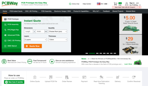
The prototyping stage is the most critical period of time for engineers, students, and hobbyists. PCBWay not only makes your boards quick but also makes your job right as well as cost-effective. This greatly reduces your cost and shortens the time for developing your electronic
PCBWay can provide 2 Layer PCBs to highly advanced HDI and flex boards. Even though the PCBs they produce differ a lot regarding functionality and areas of use. I am impressed with the quality of the boards, the delivery time, and the cost-effectiveness
The above given code is for Receiver. So now we have shared all the detail circuit diagram for transmitter and receiver and code for transmitter and receiver. If you have any doubt you can ask in the comment section. And if you don’t know how to upload the code you can refer to our article in which we have shared how to upload the code in our dinner Nano.