Hey guys, Welcome back to the Techatronic. Phone control light is very common nowadays. you can buy this fro m the market. but today we are making the same on very low cost. this phone control light can be use anywhere you have just plug it and operate with your mobile phone. there is an app which will control the light.
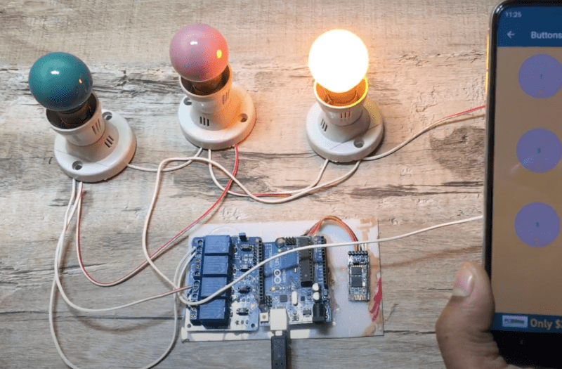
we can use this light in our bedroom, office, bathroom and anywhere we want. this will be connect by the bluetooth and using the Internet of things technology. there we have made a lot of project on the IoT technology. SO, here we are going to make a tutorial with sufficient detail to make this Control light phone project . if you really want to learn and make this project you need to follow all the steps.
Table of Contents
Introduction
The phone control light is an android app control light where you will get the application to control the light bulb. we are going to make this light with an LED bulb. which can be control with the help of same android app. for the android app we given the download link. or if you want to make the app by yourself you can refer our previous article which is WS2811 with Arduino Bluetooth control using Android app. This bulb also can be operate by the switch board. so, we will do the connection accordingly.
Phone control light will connect to the normal ac connection. It is one of the simplest example of IOT and smart automation. same as you are control this light you can control anything such as motor, fan, AC, cooler and may more things it depend on the AC load. according to the load we have to use the relay. Now there is an app which you can download by the given link and install it.
So, here are making a complete step by step tutorial for phone control lamp. the first step is know about the components which we will use in this project.
Phone control Light Components Required
| Arduino uno | BUY LINK |
| Bluetooth HC-05 | BUY LINK |
| 5v single channel Relay | BUY LINK |
| Arduino uno Cable | BUY LINK |
| jumper wires | BUY LINK |
After knowing the components we have to connect them together in write manner so, we required a circuit diagram which can help us to connect all the components.
Circuit Diagram for Phone control light

Phone control light Arduino Code
void setup() {
  // put your setup code here, to run once:
Serial.begin(9600);
pinMode(7, OUTPUT);
digitalWrite(7, HIGH);
}

void loop() {
  // put your main code here, to run repeatedly:
if(Serial.available()>0)

{

  char m= Serial.read();

  if(m=='A')
  {
digitalWrite(7, HIGH);

    }
  else
  {

    digitalWrite(7, LOW);

    }


  }
}
This is the kind fo Home automation project we have made a lot of home automation project the links are given if you are interested to learn more check these url.
WiFi Based Home Automation | NodeMCU esp8266
Home Automation using IoT | IoT project
Home automation using Arduino and bluetooth
GSM based home automation using Arduino & Sim900
These all are the different type of home automation system. you can make any one of them as per your requirements.
Working of Phone control Lamp
When we open the app and connect to the Device. that means the bluetooth of the mobile phone has been connected to the Light bluetooth both the device has been paired to each other via bluetooth communication. now the mobile can send any data to the light. basically there is some code inside the microcontroller which is Arduino here.
let suppose there is two button in app and when we press the first button the app sends the ‘A’ . now the light system receive the same. and there is a code if there is A in upcoming data then the light will be on. and when we press the second button the App will send the ‘B’ and now again the system will receive the same data and process accordingly. if the data is ‘B’ then the light will turn off.

Arduino receive the data from the bluetooth which is paired with the phone bluetooth then Arduino check and compare the data with the database. and send the command to the relay. now relay is triggered and it will turn on or turn off the light bulb. Relay is an electronic switch which can be triggered by the 5v voltage. so, here relay is working like switch. Arduino can on and off the switch for the light.
if you face any problem you can ask in the comment section. Thanks and happy learning.

