

Hello guys, welcome to techatronic with new interesting topic which is what is a resistor? and it’s types, Symbol & Examples,basically, resister is the important component in the electronic circuit. Which need in almost each and every circuit. Register has to protect the sensitive component which can damage with the voltage and current. Register absorb the extra amount of voltage or current as per the resistance value. So required the register in circuit. To use the register in many circuits first we need to know about the register like what is the register what is type symbol and example and how can we measure the resistance of a resistor.
- Resistor is the very simple and very common component of electronics. It is found in every circuit and is one of the few basic things a person should be familiar with before entering into the electronics field.
- These come in various shape size type quality and values which are discussed later in the article and the measurement and placement of them are also described in further.
- So basically there are some colour band on each type of register except smd resistor. If you want to calculate the distance of resister, we made a resistance calculator which can help you to calculate the resistance value.
Table of Contents
What is a Resistor?
Resistors are used in every circuit, either small or big, compact or large, but the difference is only of the shape, size, quality and value. Circuit has to protect it’s on component because of the excess amount of current which can damage any component like IC.
As the name of the component ‘RESISTOR’, in which ‘RESIST’ means to control or obstruct something which flows from one point of the thing to the other point.
There are many examples of resistors online like a Dam on the river or a hole in the bottle to control the flow etc. But in simple words, it controls the power flowing through it.

- The symbol for a resistor is in two different styles, left one is US and right one is EU Style. So in all circuits resistor is denoted in either way, but it may differ according to the type of it. The symbol is shown is IEC and IEEE format symbol. It is also called a fixed resistor.
- The main important thing is the unit of the resistor is the ohm, Ω there are different types of resistors some are special applications, so we can understand here what is a resistor?
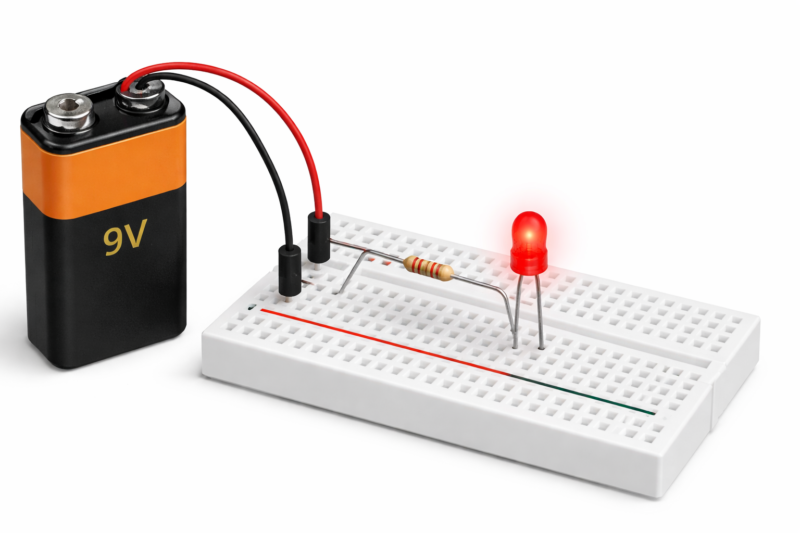
There is a very basic activity that can help you to learn the use of a resistor. Now we have a 9-volt battery and led bulb which runs on 2.2 now what will happen when we connect this led with the nine volt battery. When we connect led bulb battery due to the access amount of current the led will burn so here we required a register which need to be connect before the led so here we will explain how we can connect a resister with any device in this experiment, where connecting an led with the 9 volt battery and there is a register which need to be connected. Now how can we connect there is two terminal of led when is positive and one is negative so we can connect this resister with the positive leg of led. And the second part of the register will now be connect to the 9 volt battery 9 volt battery another terminal will directly correct to the led so how in this way we will connect a register in a single line or a series.
Basic Types Of Resistor
Fixed Resistor
- These resistors are the most common among all type of resistor and are very commonly available in the market and local electronic shops. also on online website at a very cheap rates.
- These come in many types like
- Carbon resistor
- Metal film resistor
- SMD resistor
- Wire wound resistor
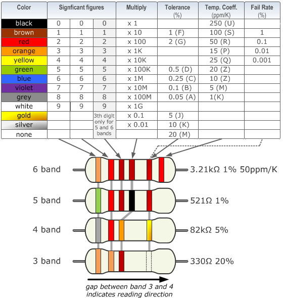
- The values of these resistors are either calculated according to the color band on the resistor or according to the code of written on the resistors, which needs to be calculated according to the Table mentioned below.
- For resistor with SMD Codes, you just have to see the first two numbers corresponding to the first two rows and the third number corresponding to the multiply column.
- The value of these resistors cannot be altered in any case, only you can connect them in series or parallel in combination to make the desired value. The calculations and combinations are discussed in furhter.
what is a resistor Carbon based:
- As the name, these resistors are made up of carbon with clay mixture bonded together to form a resistor.
- These are the most cheap ones are they are manufactures in large quantities and doesn’t require large amount of raw materials.
- These come in different shapes and size which is denoted by power ratings and are advised to use according to the usage required for each task as more power devices require large power rating resistors.
Metal film resistor:
- These resistors are made from metal which is coated onto the body of the resistor in combination with the insulating material.
- Both points are joint in such a way that each point touches the start and end of the metal film, respectively to form resistance of the desired length.
Wire-wound resistor:
- These resistors are not very common to see, as they require much more complex construction than carbon resistors.
- These resistors are made by wounding a thin wire of specific resistance around the body of the resistor to make the final piece of the desired value.
Variable Resistor
- A variable resistor as the name suggests, the values of these resistors are changeable or depend on some physical factors which are controllable by the user active or passively.
- Variable resistors are of various types, either controllable by the user or by certain other physical factors. Some of them are discussed below with their construction.
- Some of them are:
- Potentiometer
- Rheostat
- Preset
- Digital potentiometer
- Well, the purpose of all these are to supply the desired amount of either voltage or current or power. The construction may differ according to the shape and size also according to the usage.
Potentiometers:
- These are the second most commonly used resistors among beginners and hobbyists for various purposes. The shape, size, and construction of them are different according to the use and requirements.
- In the market there are various versions of them are available like:
- Single turn potentiometers, which includes a wiper-type metal strip that touches the resistance ring drawn on an insulation PCB. The resistance is various as the wiper rotates, so is the voltage and current.
- Multi-turn resistors, are used in devices that require precise resistance like BMS, Step-Up, Step down, and many other modules. These are a bit costly as compared to the single-turn ones.
- They are available in both DIP and SMD packages which is an advantage also there are many shapes and sizes and of course, values that are available in both online(easily) and offline markets.
- DIGITAL POTENTIOMETERS are similar to a potentiometer, but they use a digital signal comprised of voltage and current, as a result of using a potentiometer either.
Rheostat:
- This is the second mostly used device, particularly in labs and schools, as these devices are used in experiments. The most common WHEAT STONE BRIDGE Experiment is the lively example of it.
Preset:
- This is the small version of the potentiometer and are mostly available in sensors and modules used in various sensors. This comes in two types so far I have seen.
SMD Resistor
Ohm Law
- The resistor has been calculated in ohm. The ohm is basically the name of a German scientist. The ohm law is understood in 1827. The ohm says ohm law state that V=IR. When we talk about the ohm’s there is a question always what is a resistor
- V=IR meance the voltage is equal to the resistor and current flowing through the circuit. The ohm law uses in three-way as shown in fig. The triangle shown in fig is very useful for better understanding. Calculated the resistor value by the ohm law.
- Example-shown in below, circuit finds us the value of resistor by using ohm law.
- In-circuit shows the voltage of the given circuit is 5volt and current is 1ampere resistor calculated by simple formula that is V=IR
- Then find out the resistor equation will be R=V/i that is 5/1=0.2ohm the value of the resistor needed in-circuit is 0.2 ohm. So the ohm law play the important role in resistor and also electronic circuit.
- Practically give A simple circuit much time we will try them in our home consider the simple circuit for better understanding
Ohm’s law is normally used to calculate the resistance.
Ohm’s Law is one of the most fundamental principles in electrical and electronics engineering. It explains the relationship between voltage (V), current (I), and resistance (R) in an electrical circuit. The law was formulated by the German physicist Georg Simon Ohm in 1827.
Ohm’s Law states that the current flowing through a conductor is directly proportional to the voltage applied across it and inversely proportional to its resistance, provided the temperature remains constant. In simple words, if you increase the voltage, the current increases. If you increase the resistance, the current decreases.
The mathematical formula of Ohm’s Law is:
V = I × R
Where:
V = Voltage (measured in volts)
I = Current (measured in amperes)
R = Resistance (measured in ohms, Ω)
Using this formula, we can also write:
I = V / R
R = V / I
Ohm’s Law is widely used in circuit analysis, designing electrical systems, and troubleshooting electronic devices. For example, if a 9V battery is connected to a 3Ω resistor, the current flowing through the circuit will be 3 amperes (9 ÷ 3 = 3A).
Now any confusion on what is a resistor? you can ask us in the comment section