
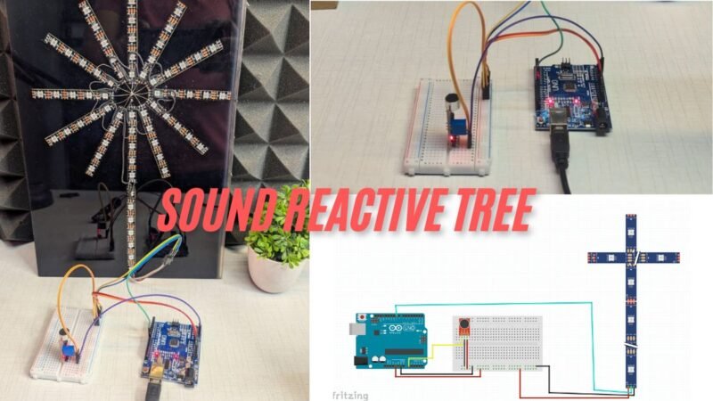
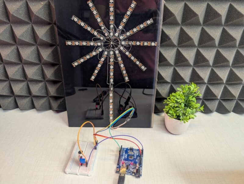
Hey Guys welcome back to the Techatronic. I am making a Learn how to build a sound reactive RGB tree using Arduino and WS2812 LEDs. Create music-sync lighting effects with circuit and code. which is very interesting and trending. We are sharing all the details here. how wee made this. So basically, this is another version of the sound reactive project. in this we take a pixel strip ws2812 and connect to the arduino. and one sound sensor too. which will control the colour and light. this is very simple and interesting project.
we will going to share all the detail for this project in this article. also we will share all the components list so you can buy easily and make your own project. this is actually a interesting project which can be used in car , home, studio and many other places. we are using the 2812 strip which is widely used in the world of rgb lighting. and the controllers are very expensive. but we did in very less amount. so, if you want to control this strip by your controller you can refer this article. we did the same type of project before. you can check the more detail there.
Introduction on Sound Reactive RGB Tree
he Pixel RGB LED Tree Drop Sound Reactive project is an exciting combination of electronics, creativity, and interactive lighting effects. This project transforms ordinary RGB addressable LEDs into a visually stunning display that reacts in real time to sound, making it perfect for decorations, events, music setups, and DIY smart lighting systems. By using pixel RGB LEDs arranged in a tree-drop pattern, the lighting effect creates a dynamic waterfall or falling-light illusion that comes alive with audio input.
In this project, sound signals captured through a microphone module are processed by a microcontroller such as Arduino to control the brightness, color, and movement of the RGB LEDs. Whenever music, claps, or ambient sound is detected, the LEDs respond instantly by changing patterns, colors, or intensity. This sound-reactive behavior makes the project highly interactive and visually engaging, especially in dark environments or during music playback.
The Pixel RGB LED Tree Drop design is popular for festive decorations, stage lighting, home automation displays, and DIY art installations. Because addressable RGB LEDs allow individual control of each pixel, the project offers endless customization options. You can create smooth color transitions, beat-based animations, and cascading drop effects synchronized with sound frequencies.
This blog post explains the complete working principle of the Pixel RGB LED Tree Drop Sound Reactive project, including required components, circuit connections, and basic programming logic. Whether you are a beginner exploring Arduino projects or an electronics enthusiast looking to build a creative lighting system, this project is a perfect blend of fun and learning. By the end of this guide, you will understand how sound-reactive lighting works and how to build your own stunning RGB LED tree drop effect.
Now we need to know the components’ details. also you can buy the components from our website.
Components Required for Sound Reactive RGB Tree
| Components Name | Buy Link |
| Arduino Uno | BUY NOW |
| WS2812 Strip | BUY NOW |
| Microphone sensor | BUY NOW |
| Jumper Wire | BUY NOW |
| BreadBoard | BUY NOW |
| Arduino Cable | BUY NOW |
if you want to order full kit you can order it too – Buy Full Kit
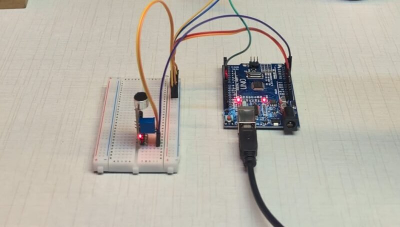
here, we have given the all components details. now we need to assemble the components. to assemble the components we need a circuit digram.
Circuit Diagram Sound Reactive RGB Tree
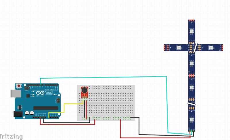
his circuit is for a Sound Reactive RGB Tree Drop Effect using:
- Arduino UNO
- Sound sensor (microphone module)
- WS2812 / WS2812B RGB LED strip (Tree Drop style)
- Breadboard & jumper wires
The Arduino reads sound data from the microphone and controls the RGB LED strip to create sound-based lighting effects.
🧠 Main Components and Their Roles
1️⃣ Arduino UNO (Controller)
- Acts as the brain of the project.
- Reads analog sound signals from the microphone.
- Sends digital data signals to the WS2812 LED strip to control colors and animations.
2️⃣ Sound Sensor / Microphone Module
- Detects sound, music, or beats from the environment.
- Converts sound into an analog electrical signal.
- This signal is read by the Arduino to decide how the LEDs should react.
3️⃣ WS2812 RGB LED Tree Drop Strip
- Addressable RGB LEDs where each LED can be controlled individually.
- Uses one data pin to receive color and brightness instructions from Arduino.
- Creates cascading, tree-drop, and sound-reactive effects.
🔗 Circuit Connections Explained
🔹 Sound Sensor Connections
- VCC → Arduino 5V
- GND → Arduino GND
- OUT → Arduino Analog Pin (A0)
- This pin sends sound intensity data to Arduino.
🔹 WS2812 RGB LED Strip Connections
- +5V → Arduino 5V (or external 5V supply for more LEDs)
- GND → Arduino GND
- DIN (Data In) → Arduino Digital Pin (e.g., D6 or D7)
- This pin carries LED control data.
⚠️ Important:
Arduino GND, sound sensor GND, and LED strip GND must be common. This is essential for proper working.
🔹 Breadboard Usage
- Used to:
- Distribute 5V and GND
- Connect the microphone module easily
- Keep wiring clean and organized
After complete the connection part now we will need the Code.
How the Circuit Works (Step-by-Step)
- The sound sensor detects audio (music, clap, noise).
- It sends an analog signal to Arduino A0.
- Arduino processes this signal in the code.
- Based on sound intensity:
- LED colors change andf make drop on every beats
- Brightness increases/decreases
- Drop or cascade effects are triggered
- Arduino sends control data to the WS2812 LED strip.
- LEDs react in real time to sound 🎵✨
Sound Reactive RGB Tree code
// Motor control pins
const int motorPin1 = 2;  // Motor 1 IN1
const int motorPin2 = 3;  // Motor 1 IN2
const int motorPin3 = 4;  // Motor 2 IN1
const int motorPin4 = 5;  // Motor 2 IN2
const int enablePin = 10; // Shared enable pin

// Analog input
const int analogInput = A0;
int previousState = 0; // 0: neutral, 1: clockwise, -1: anti-clockwise

// Ultrasonic Sensor 1 (for Motor 1)
const int trigPin1 = 7;
const int echoPin1 = 8;

// Ultrasonic Sensor 2 (for Motor 2)
const int trigPin2 = 10;
const int echoPin2 = 11;

// Distance threshold (in cm)
const int distanceThreshold = 15;

// Direction tracking for Motor 2
int motor2Direction = 1; // 1 = clockwise, -1 = anticlockwise
unsigned long lastToggleTime = 0;
const unsigned long toggleDelay = 500; // 1 second cooldown

void setup() {
  pinMode(motorPin1, OUTPUT);
  pinMode(motorPin2, OUTPUT);
  pinMode(motorPin3, OUTPUT);
  pinMode(motorPin4, OUTPUT);
  pinMode(enablePin, OUTPUT);

  pinMode(trigPin1, OUTPUT);
  pinMode(echoPin1, INPUT);
  pinMode(trigPin2, OUTPUT);
  pinMode(echoPin2, INPUT);

  digitalWrite(motorPin1, LOW);
  digitalWrite(motorPin2, LOW);
  digitalWrite(motorPin3, LOW);
  digitalWrite(motorPin4, LOW);
  analogWrite(enablePin, 0);

  Serial.begin(9600);
}

void loop() {
  int sensorValue = analogRead(analogInput);
  Serial.print("Analog: ");
  Serial.println(sensorValue);

  long distance1 = getDistance(trigPin1, echoPin1);
  long distance2 = getDistance(trigPin2, echoPin2);

  // 🚨 SAFETY STOP
  if ((distance1 > 0 && distance1 <= distanceThreshold) ||
      (distance2 > 0 && distance2 <= distanceThreshold)) {

    Serial.println("Obstacle detected within 15 cm → STOP ALL MOTORS");
    stopMotors();
    delay(100);
    return;  // DO NOT execute motor logic
  }

  // -------- NORMAL OPERATION --------
  if (sensorValue > 200) {
    rotateMotor(1);
    delay(300);
    rotateMotor(-1);
    delay(300);
  }
}


void rotateMotor(int direction) {
  if (direction == 1) {
    // Clockwise
    digitalWrite(motorPin1, HIGH);
    digitalWrite(motorPin2, LOW);
    digitalWrite(motorPin3, LOW);
    digitalWrite(motorPin4, HIGH);
  } else if (direction == -1) {
    // Anticlockwise
    digitalWrite(motorPin1, LOW);
    digitalWrite(motorPin2, HIGH);
    digitalWrite(motorPin3, HIGH);
    digitalWrite(motorPin4, LOW);
  }

  analogWrite(enablePin, 150);
  delay(200);
  stopMotors();
}

void rotateSingleMotor(int in1, int in2, int direction) {
  if (direction == 1) {
    digitalWrite(in1, HIGH);
    digitalWrite(in2, LOW);
  } else {
    digitalWrite(in1, LOW);
    digitalWrite(in2, HIGH);
  }

  analogWrite(enablePin, 150);
  delay(200);
  digitalWrite(in1, LOW);
  digitalWrite(in2, LOW);
  analogWrite(enablePin, 0);
}

void stopMotors() {
  digitalWrite(motorPin1, LOW);
  digitalWrite(motorPin2, LOW);
  digitalWrite(motorPin3, LOW);
  digitalWrite(motorPin4, LOW);
  analogWrite(enablePin, 0);
}

long getDistance(int trigPin, int echoPin) {
  digitalWrite(trigPin, LOW);
  delayMicroseconds(2);
  digitalWrite(trigPin, HIGH);
  delayMicroseconds(10);
  digitalWrite(trigPin, LOW);

  long duration = pulseIn(echoPin, HIGH, 30000); // Timeout after 30ms
  long distance = duration * 0.034 / 2;
  return distance;
}
here we have share the code now you need to upload the code into your arduino using arduino cable.
Applications of This Circuit
- Sound reactive LED decoration
- Pixel RGB tree drop effects
- Party and DJ lighting
- Stage and festival decoration
- DIY Arduino projects