Hey guys , welcome back to the Techatronic. Smart helmet has many features like Navigation, Call , accident detection , alcohol detection and many more feature to make this helmet as a smart helmet. As we consider the safety and security of the driver this helmet can help a lot. such as if you are drunk you can’t start the bike. so, it is reloaded with the lots of features. the main aim to make this smart helmet project to the safety of the driver.
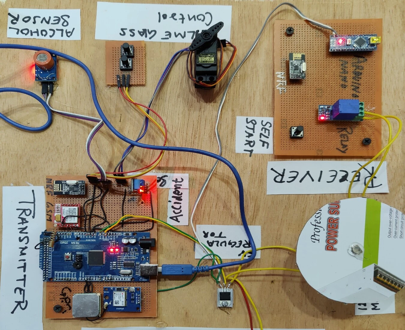
This helmet is made up of many electronic components such as GPS, GSM, and other sensors. also, we required a working 2G, 3G sim for gsm module. we always try to solve a community problem with our innovation we have made many project earlier such as Sign language glove, blind stick , etc. In this smart helmet.
This is very unique idea with the helmet, accident detection smart helmet project using Arduino. This helmet can prevent the accident damage to the driver. also it will call to your relative adn send the location through GSM module.
Table of Contents
How does the system will work?
First we will talk about the transmitter part. this will deploye in the helmet there is two sensor we used alcohol sensor and accident detection sensor. Alcohol sensor which also known as the mq3 sensor. let learn something about the sensor.

Components Required for smart helmet :-
MQ3 sensor (Alcohol Sensor)
MQ3 sensor is a special kind of sensor that can only sense the alcohol from the moisture in the air. the moisture content of alcohol can be detected by the sensor. inside the sensor, there is a metal electrode that can be activated when comes into contact with the alcohol.
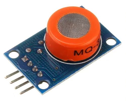
there is electron flow between the electrode used inside the mq3 sensor. when the sensor comes in contact with alcohol the conductivity of the same electrode will be high.this sensor wil help in this smart helmet project using arduino that can be detected at the output pin. so, we can connect this mq3 sensor with Arduino or whatever controller we are suing here.
MQ3 sensor input voltage is 5V which can be given by the Vcc pin of the sensor. mq3 sensor may be malfunction when we use it for hours.
Vibration Sensor SW-420
The other important sensor is Vibration sensor. the model number is SW-420 for the given vibration sensor. the working of the vibration sensor is very simple.

there is a lot small metal balls inside the cylindrical shape enclosed. inside the sensor there is many metal line. each of the two line connected to the ground and signal wire. when there is vibration occours the ball touches both the lines and conduct the electricity and give the signal at output pin.
this vibration sensor will be used to trigger the gsm module. vibration sensor continuously send the signal to the arduino. Arduino is our microcontroller in this smart helmet project. if any rise in the signal it the arduino will take the action according to the signal
If the sensor sense a vibration in the smart helmet which is nearly to the accident. the Arduino trigger the gsm module to send the message and call.
GSM SIM800L Module.
We use GSM SIM800L Module in this smart helmet project to navigate the location. it will be triggered with the vibration sensor.
GSM SIM800L is a low power module which support 2g 3g sim for communication.
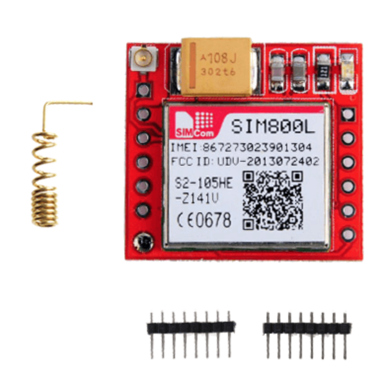
The GSM SIM800L module is small in size and low cost GSM module that allows you to connect your device to the gsm network. it have the ability to communicate with other devices via SMS, voice calls, or GPRS. there are quad bands given that can be supports 850/900/1800/1900 MHz frequency bands.
Sim800l module can be run over the 2g and 3g band. The module support the UART protocol. to enable the protocol there is two pin Rx and Tx. by these pin the module transfer and receive the data.
It runs from 3.3 volts to 5v but need at least 2 amp power. i suggest give 5v 2amp external power supply. to power the mmodule.
If you want to program the gsm module list AT commands for instructions we give all the instrcustion given below.
| Command | Description |
| AT+CSMS | To Select message service |
| AT+CPMS | To Preferred message storage |
| AT+CMGF | select Message format |
| AT+CSCA | Service center address |
| AT+CSMP | Set text mode parameters in sim |
| AT+CSDH | To Show text mode parameters in Sim |
| AT+CSCB | Select cell broadcast message types |
| AT+CSAS | Save settings in the gsm module |
| AT+CRES | Restore all settings |
| AT+CNMI | Message indications to TE |
| AT+CMGL | To make the list of messages |
| AT+CMGR | Read new message |
| AT+CMGS | Send a new message |
| AT+CMSS | Send message from sim storage |
| AT+CMGW | Write a message to gsm memory |
| AT+CMGD | Delete message |
Keep in mind that while the module is relatively easy to use, it requires some knowledge of electronics and programming. You will also need to ensure that you have a compatible SIM card and a stable cellular network connection in your area.
we will add the phone number inside the program on which the sms and call will be sent.
GPS Module neo 6m module
Neo 6M module is use for sending the current location in this arduino based helmet project.
The NEO-6M GPS module is a low cost and small size module which can receive the gps signal and can be provide position with lattitude and longitude with time. it work with the global positioning system also it supports global navigation satelite system.
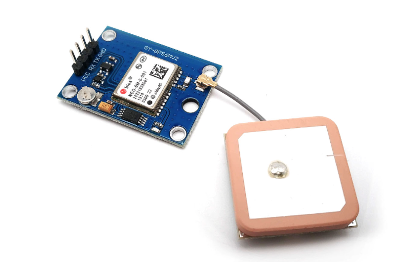
The gps neo 6m module can be communicate with any microcontroller with the UART protocol in this project this module will be connect to the arduino with the UART protocol and use rx and tx pin to connect the system.
There is a library which can help to callibrate the sensor with the coding.
Some common applications for the NEO-6M GPS module include navigation systems, geotagging, tracking devices, and unmanned aerial vehicles (UAVs). It is important to note that the module requires a clear view of the sky to receive GPS signals, and may not work well indoors or in areas with poor satellite coverage.
NRF module NRF24L01
There are two device in this smart helmet project one is transmitter and other is receiver in both of them we need to transmit the data. so we are using NRF module to bidirectional communication.
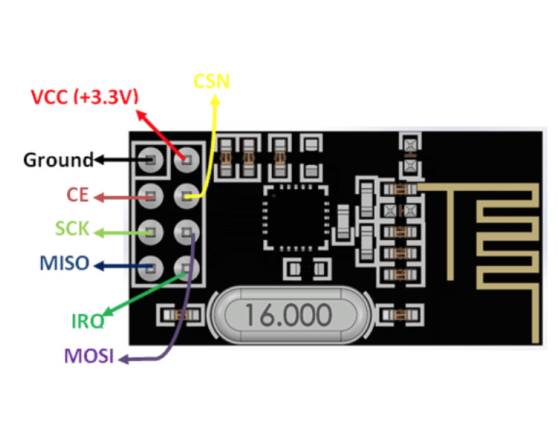
NRF module are the small size low cost ultra power module that works 2.4 GHZ wireless transreceiver. that can be use in wireless communication project. you can also connect many nrf module together and make commuincation between all the NRF Module.
NRF module use the SPI (serial peripheral interface ) protocol to make the communication between all the device we have two nrf moduel one will be connect to the transmitter and other will be connect to the receiver module.
Single channel Relay module
Here in the receiver section we are using a relay which will be trigger the motor which is to be pretend the bike engine.
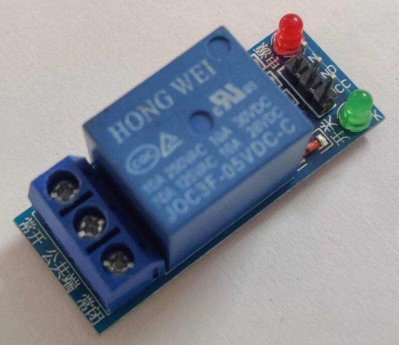
when it receive the data from the tranmitter and start the motor it need to be trigger by the relay module. relay module will be use to operate the 12v DC motor.
DC motor 12v
We are using here 12v dc motor with gears . If the driver is drung the motor will be turn off. it means the bike engine will be turn off.
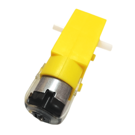
12v dc motor connected via 12v external poswer supply. which is connected through the relay which always will be triggered from the relay. Arduino can’t run a dc motor due to back emf and low current at the pins.
Arduino Mega for Tranmitter
We are using Arduino mega at the trnamitter site. there is many electronic components which need to be connect with the different communication protocol. such as NRF, GSM, GPS and other.
Arduino mega has more than 60 pins to communicati with the devices so it will be compatible with our project.
Arduino Nano
The Arduino Nano is a small and compact microcontroller board based on the Atmel ATmega328P microcontroller chip. It is similar to the popular Arduino Uno board but comes in a smaller form factor. The board is designed to be easily programmable through the Arduino Integrated Development Environment (IDE) using a USB connection.
Smart Helmet Project Circuit Diagram (Transmitter)
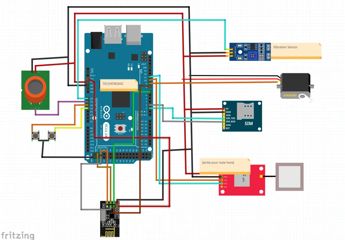
Here we have given the circuit diagram for smart helmet receiver circuit. alcohool sensor, push button , servo motor , gps, gsm and NRF module.
Connection Table
| Arduino Mega | MQ-3 Alcohol Sensor |
| 5V | VCC |
| G, GND | GND |
| A0 Pin | A0 Pin |
| Servo motor | |
| 5V | Red |
| GND | Black |
| DATA | Orange |
| GSM SIM800L | |
| 2 | Rx |
| 3 | Tx |
| 5v | Vcc |
| GND | Gnd |
| GPS NEO 6M Module | |
| 10 | Rx |
| 11 | Tx |
| 5v | Vcc |
| GND | Gnd |
| Vibration Sensor | |
| A1 | Din |
| 5v | Vcc |
| Gnd | Gnd |
| NRF Module | |
| 50 | MISO |
| 51 | MOSI |
| 52 | SCK |
| 8 | CSN |
| 7 | CE |
| 3.3V | Vcc |
| Gnd | Gnd |
Now we have to make the Transmitter connection to complete the project.
Smart Helmet Project Circuit Diagram (Receiver)

Connection Table
| Arduino Nano | Relay Module |
| D6 | In |
| 5v | Vcc |
| Gnd | Gnd |
| NRF 24L01 | |
| 12 | MISO |
| 11 | MOSI |
| 13 | SCK |
| 7 | CE |
| 8 | CSN |
| 3.3v | Vcc |
| Gnd | Gnd |
Smart Helmet Project Code
Code for Transmitter part.
before upload the code you need to import some library.
#include <SPI.h>
#include <nRF24L01.h>
#include <RF24.h>
#include <TinyGPS.h>
#include <Servo.h>
 #include<SoftwareSerial.h>

RF24 radio(7, 8); // CE, CSN

const byte address[6] = "00001";


Servo myservo;

int pos = 0;


int state = 0;
const int pin = A1;
float gpslat, gpslon;

TinyGPS gps;
SoftwareSerial sgps(10, 11);
SoftwareSerial sgsm(2, 3);

void setup() {
  // put your setup code here, to run once:
pinMode(A0, INPUT_PULLUP);
pinMode(A1, INPUT_PULLUP);
pinMode(A2, INPUT_PULLUP);
pinMode(A3, INPUT_PULLUP);
 myservo.attach(9);

sgsm.begin(9600);
  sgps.begin(9600);

  radio.begin();
  radio.openWritingPipe(address);
  radio.setPALevel(RF24_PA_MIN);
  radio.stopListening();

Serial.begin(9600);
 myservo.write(180);
 delay(500);


}

void loop() {


  // put your main code here, to run repeatedly:
int m = analogRead(A0);
int n = analogRead(A1);
int o =digitalRead(A2);
int p =digitalRead(A3);
Serial.print(m);
Serial.print("    ");
Serial.print(o);
Serial.print("    ");
Serial.print(n);
Serial.print("    ");
Serial.println(p);
delay(100);

if(o==0)
{
  myservo.write(180);
 delay(500);


  }

  else if (p==0)

  {
     myservo.write(0);
 delay(500);

    }


sgps.listen();
  while (sgps.available())
  {
    int c = sgps.read();
    if (gps.encode(c))
    {
      gps.f_get_position(&gpslat, &gpslon);
    }
  }


if(m>=500)
{
   const char text[] = "H";
  radio.write(&text, sizeof(text));
  delay(100);

  }

  else
{
   const char text[] = "A";
  radio.write(&text, sizeof(text));
  delay(100);

  }

  if(n>=700)

  {

    sgsm.listen();
      sgsm.print("\r");
      delay(1000);
      sgsm.print("AT+CMGF=1\r");
      delay(1000);
      /*Replace XXXXXXXXXX to 10 digit mobile number &
        ZZ to 2 digit country code*/
      sgsm.print("AT+CMGS=\"+919560718291\"\r");
      delay(1000);
      //The text of the message to be sent.
      sgsm.print("Latitude :");
      sgsm.println(gpslat, 6);
      sgsm.print("Longitude:");
      sgsm.println(gpslon, 6);
      delay(1000);
      sgsm.write(0x1A);
      delay(4000);
 sgsm.println("ATD +919560718291;"); //replace x by your number
   delay(20000);
   //digitalWrite(5,HIGH);  // LED1 ON
   sgsm.println("ATH");
   delay(2000);
   Serial.println("calling.....");


    }

    else
    {
      Serial.print("");

      }


}
After uploading the given code into the tranmitter part of the project. you need to upload the given code into the Receiver section.
Smart helmet code for Receiver
#include <SPI.h>
#include <nRF24L01.h>
#include <RF24.h>

RF24 radio(7, 8); // CE, CSN

const byte address[6] = "00001";

void setup() {
  pinMode(6, OUTPUT);
   pinMode(3, INPUT_PULLUP);
  Serial.begin(9600);
  radio.begin();
  radio.openReadingPipe(0, address);
  radio.setPALevel(RF24_PA_MIN);
  radio.startListening();
}

void loop() {

  int c= digitalRead(3);
  if(c==0)

  {

    while(1)
    {
  if (radio.available()) {

    char m;
    radio.read(&m, sizeof(m));
    Serial.println(m);
    //char m = text;


    if(m=='H')
    {
      while(1)
      {
      digitalWrite(6, HIGH );
    delay(200);

 int c= digitalRead(3);
  if(c==0)
  {


    break;}


      }

      }


      else if(m=='A')
 {

      digitalWrite(6, LOW );
    delay(200);


      }

  }
    }

  }

else

{


      digitalWrite(6, HIGH );
    delay(200);
  }


}
Both the code is given here. only you need to import the libraries and upload the code into both circuits. if do you have any problem or doubt you can ask us in the comment section.
Application of Smart Helmet project.
It can wear during bike ride, scooter ride.
it can also use to track the rider.
it can also use to call cut and receive automatically
Advantage of smart helmet
It help to protect the rider head from the accident
it also can help to avoid drink and drive there is a sensor which can sense the driver is drunk of not.
it can also help to wear the helmet for ride without helmet the bike will not start
smart help can send the location of the rider if there is any mishappening occours
FAQ’s
Q:- Which sensor use to detect the person wear helmet or not.
A:- there is ir sensor inside the helmet which can monitor rider wear helmet or not
Q:- may the smart helmet work in rain?
A:- yes , the smart helmet using all waterproof components so, it is waterproof
Q:- Smart helmet is connect to the bike?
A:-yes, the smart helmet is connected to the mobile phone
Video Hint:-
