Table of Contents
Introduction
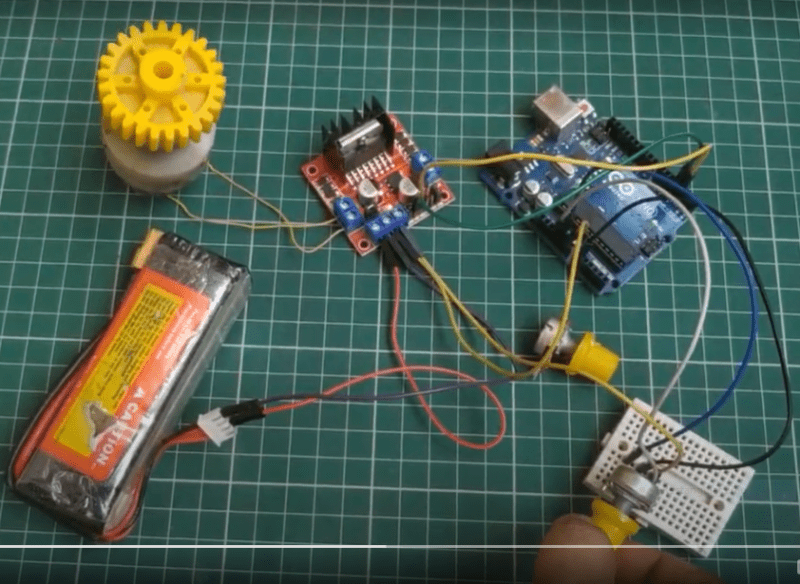
Hello geeks, welcome back to Techatronic. In this article, we are going to teach you a very interesting project that is how to make a DC motor speed control circuit using Arduino UNO. We are using an L298N motor driver module here for interfacing with the DC motor. You can not regulate the speed of a DC motor directly but using this circuit it is possible to do so. Complete the circuit and then upload the code to the Arduino. You can also check more such amazing projects based on Arduino and IoT. The image of the complete project is also given below.
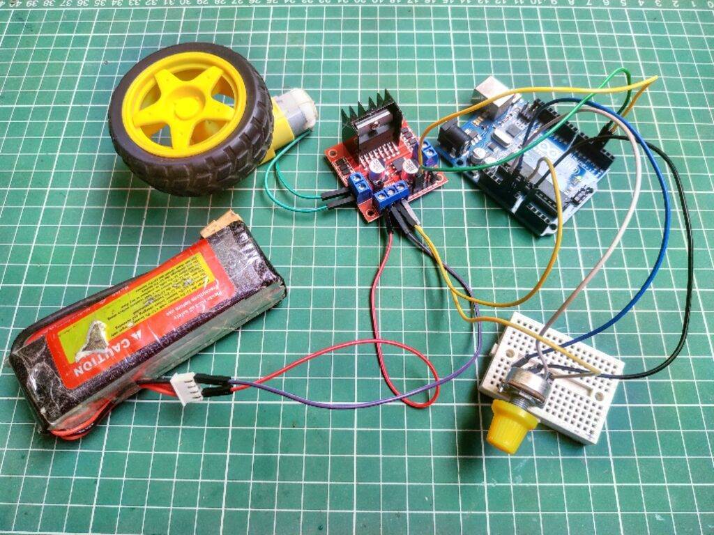
DC Motor Speed Control Working
Generally, DC motors rotate at a constant speed(RPM) in clockwise or anticlockwise directions depending upon the polarity of the current that is provided to it. In this project, we are trying to slow down or boost the speed of the motor with the help of an Arduino board. The potentiometer that we are using is responsible for the speed of the motor. You can rotate the potentiometer and the speed of the motor varies accordingly. this is the 10th blog in the Arduino tutorial. The Arduino generates control signals based on the input from the variable resistor but the motor can not process them directly so we are using an L298N motor driver. This driver module provides the correct output signals so the motor can rotate perfectly. You can check the output values generated by the variable resistor on the serial monitor screen. The screenshots of the serial monitor screen are also given below so that you can locate it on your IDE software.
Serial Communication simulation


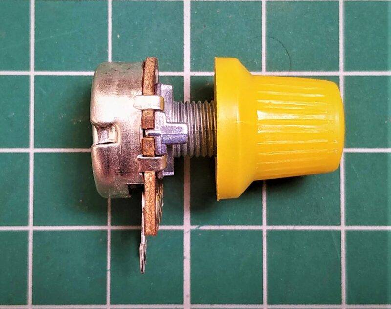
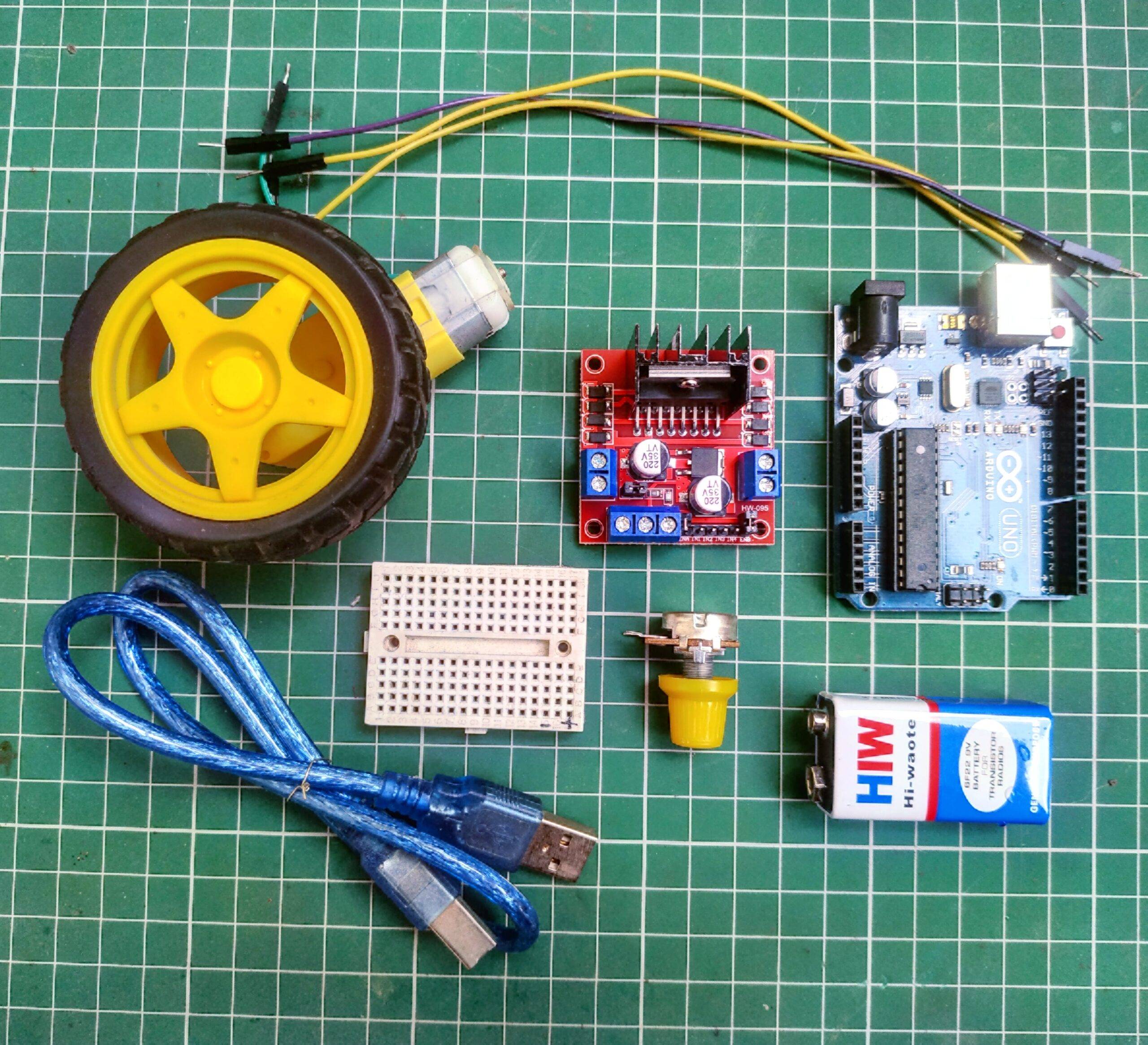
Components Required
you can buy all components together-BUY LINK
| Arduino UNO | BUY LINK |
| DC motor | BUY LINK |
| Jumper wires | BUY LINK |
| breadboard | BUY LINK |
| 9 volts battery | BUY LINK |
| 10K potentiometer | BUY LINK |
| USB cable for uploading the code | BUY LINK |
| L298n motor driver | BUY LINK |
| Wheel | BUY LINK |
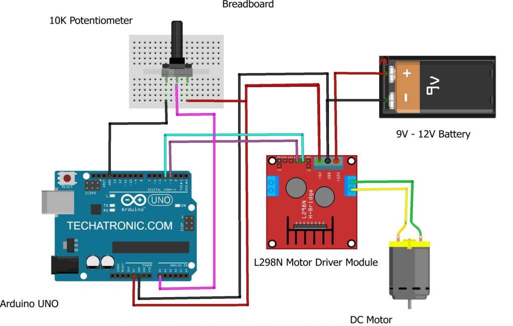
DC Motor Speed Control Circuit Diagram
Connection Table
| Arduino UNO | 10 K Potentiometer | |
| VCC | Terminal 1 | |
| A0 Pin | Terminal 2 | |
| GND | Terminal 3 | |
| Motor | L298N Motor Driver | |
| Terminal 1 | Terminal 1 Output | |
| Terminal 2 | Terminal 2 Output | |
| Arduino UNO | 9 Volt Battery | L298N Motor Driver |
| Positive | +12 | |
| ( +5V ) VCC | + 5 | |
| GND | Negative | GND |
| 9 Pin | IN 1 | |
| 8 Pin | IN 2 |

Connect 5 volts pin of the Arduino with the 5 volts pin of the L298n motor driver module and one side pin of the 10K ohm potentiometer. Attach the GND pin of the Arduino with the GND pin of the L298n module and another side pin of the 10K potentiometer. Join the middle pin of the potentiometer with the analog-0 pin of the Arduino. Take a 9 volts battery and connect its positive wire with the 12 volts pin of the L298n module and its negative wire with the GND pin of the Arduino. Join the IN1 pin of the motor driver module with the digital-4 pin of the Arduino and the IN2 pin of the driver module with the digital-3 pin of the Arduino. At last, take a DC motor and connect its wires with the output pins of the driver module. The circuit is now completed, power the Arduino and DC motor start rotating.
DC Motor Speed Control Arduino Code
NOTE: Please upload the code which is given below to the Arduino.
 // TECHATRONIC.COM
 void setup()
  {
  Serial.begin(9600);
   pinMode(3,OUTPUT); // Motor pin 1
   pinMode(4,OUTPUT); // Motor pin 2
   digitalWrite(4,LOW); // Normally LOW inthis pin
   pinMode(A0,INPUT);  // 10k Potentiometer
  }
  void loop()
  {
  int s=analogRead(A0); // 10k Potentiometer
  int z=map(s,0,1024,0,255);
  Serial.println(z);
  analogWrite(3,z);
  }
We hope that you like this project on DC motor speed control and now try to make it on your own so that you can understand it better. If you have any doubts regarding this project then do inform us in the comments section below. Also, check out the latest tutorials on Arduino and Raspberry Pi.
HAPPY LEARNING!