Fastest Finger First 555 timer Project | 555 IC mini project
Hey guys, hope you are doing fine. Are you searching to make a circuit for quiz competitions? Well in this article we are going to teach you how to make the Fastest Finger First 555 timer Project. Before starting please check the brief introduction to 555 ic. This circuit can be used in quiz competitions and other group activities. Also, do check out the latest project on Arduino and Raspberry pi made by us.

fastest finger first 555 ic mini project Working?
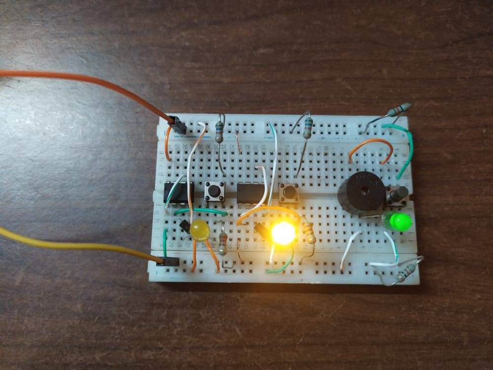
- As the name suggests there are some pushbuttons that have to be pressed and the team which presses the button first will allow to speak first. In this fastest finger first circuit,
- we are making the setup for two teams only as it is a demo but you can add up as many setups as you want. There is an LED for each team that glows when the button is pressed. Once the LED of any team is turned on then no other team will be allowed to speak as the LED for other teams will not glow if they push the button later.
- This is a very good 555 project There is a status LED that indicates that someone has pressed the button or the LED of someone’s team is on. We can also reset all the LEDs by pressing the reset button.

Components Required
- Three or more 555 timer IC’s
- Pushbuttons
- 10K, 1K, 220-ohm resistors
- Connecting wires and a breadboard
- LEDs and IN4007 diodes
- 9 volts battery
555 timer Circuit Diagram

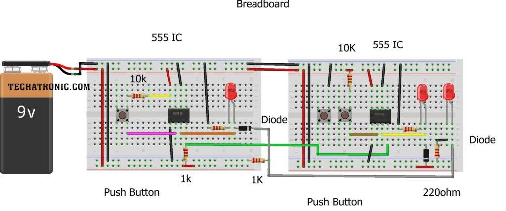
- If you are using a breadboard in this Fastest Finger First 555 timer Project then use the first two rails as positive power supply rail and reset rail and the second two rails as negative power supply rail and feedback rail.
- Then connect a 1K-ohm resistor between positive and reset rail and another 1K-ohm resistor between negative and the feedback rail.
- Place a 555 timer ic on the breadboard and connect its pin 1 to the negative rail and pin 8 to the positive rail.
- Join pin 1 and 6 together. Now place a pushbutton on the breadboard and connect a wire between the negative rail and a pair of interconnected pins.
- Connect the other pair of interconnected pins with the positive rail via a 10K-ohm resistor.
- Join pin 2 of the ic with the pin of the pushbutton connected with the positive rail. Attach pin 4 with the reset rail on the breadboard.
- Now put an in4007 diode between pin 3 and the feedback rail such that its negative terminal is towards the feedback rail.
- Join the positive leg of the LED with pin 3 and the negative leg with the negative rail via a 220-ohm resistor.
You can make as many modules as you want by repeating the same connections in the 555 ic mini-project. Join the pair of interconnected pins of the last pushbutton with the negative rail and the other inter-connected pins with the reset rail. At last, take an LED and connect its positive leg with the feedback rail and the negative leg with the negative rail via a 220-ohm resistor.
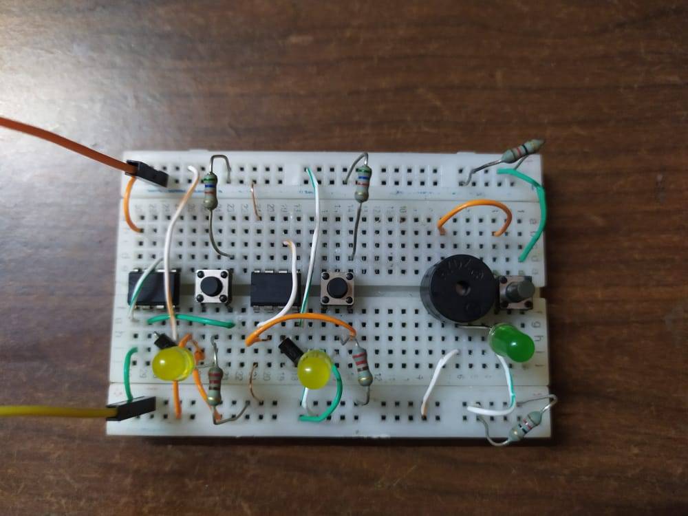
We hope that you like this fastest finger first circuit and if you have any doubts regarding the project then please ping us in the comments section below.
HAPPY LEARNING!
Latest 555 timer Projects
555 PWM Motor Speed Control | 555 PWM |555 PWM Generator
Cell Phone Signal Jammer Using 555 IC | 555 timer project signal jammer


