

Hello there, do you want to make your own Color Detector Using Arduino and TCS 230 Color Sensor. If so, you have come to the right destination. In this article, we will learn how the TCS 230 Color Sensor works with Arduino. In this project, we use TCS 230 sensor to detect the color and a 16X2 LCD to display the name of the color. We use five LEDs of different colors so the LED of the detected color will glow automatically. You can also use an I2C module for interfacing the LCD with Arduino. If you are new to this field and want to make such cool Arduino projects then click here. Arduino is a microcontroller that uses ATmega 328p ic for its functioning. There are many variants of Arduino available in the market but we use Arduino UNO in this project.
How Does it Work?
In this project, we use TCS 230 Color Sensor for differentiating between various colors. If you are not familiar with the color sensor please go through the working of the TCS 230 color sensor with Arduino. When we put the specific color tag over the color sensor then it detects its color and the results can be seen on the LCD screen. For interfacing LCD with Arduino, you can use an I2C module. The name of the captured color is displayed on the LCD. We use LEDs of five different colors like Red, White, Green, Yellow, and Blue so that only that LED will glow whose color is the same as the captured color. Make the connections as given below and upload the Arduino code. In this way, the project works and displays the captured results at the same time on LCD.
Components Required
- Arduino UNO
- USB Cable for Uploading the Arduino Code
- 10 K potentiometer
- 2X16 LCD
- Breadboard
- Jumper Wires
- TCS 3200 Color Sensor
- Resistors of 220-ohm
- LED of Red, Blue, Green, White, and Yellow
| Arduino UNO | BUY LINK |
| USB Cable for Uploading the Arduino Code | BUY LINK |
| 10 K potentiometer | BUY LINK |
| 2X16 LCD | BUY LINK |
| Breadboard | BUY LINK |
| Jumper Wires | BUY LINK |
| TCS 3200 Color Sensor | BUY LINK |
| Resistors of 220-ohm | BUY LINK |
| LED of Red, Blue, Green, White, and Yellow | BUY LINK |
You can buy all components together-BUY LINK
Circuit Diagram of the Project
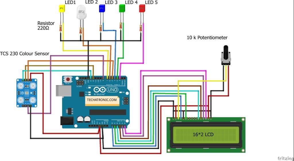
Make the connections according to the circuit diagram given above. Connect the 5 Volt and GND pin of the Arduino to the VCC and GND of the TCS 230 color sensor. Attach the 5 Volt and GND pin of the Arduino to the LCD as shown above. Connect a 10K potentiometer to the LCD. Join the Analog 0 to 5 pins of the Arduino to the LCD as shown. Connect the OUT, S2, and S3 pins of the color sensor to the digital 5, 12, and 13 pins of the Arduino. Connect the 0E pin of the color sensor to the digital 8 pin of the Arduino. Attach the negative legs of all the LEDs to the GND pin of the Arduino through a 220-ohm resistor for each LED. Connect the positive leg of Red, Green, Blue, White, and Yellow to the digital 2, 3, 4, 6, and 7 pins of the Arduino.
Code of the Project
NOTE: Upload the given code to the Arduino. You have to install <LiquidCrystal.h>, <MD-TCS230.h> and <FreqCount.h> .
 // TECHATRONIC.COM
 // LIBRARY MD_TCS230
 // https://github.com/MajicDesigns/MD_TCS230
 // LIBRARY FreqCount
 // https://github.com/PaulStoffregen/FreqCount
 #include "LiquidCrystal.h"
 LiquidCrystal lcd(A0, A1, A2, A3, A4, A5);
 #include <MD_TCS230.h>
 #include <FreqCount.h>
 int Red,Green,Blue; // Pin definitions
 #define S2_OUT 12
 #define S3_OUT 13
 #define OE_OUT  8  // LOW = ENABLED
 MD_TCS230 CS(S2_OUT, S3_OUT, OE_OUT);
 void setup()
 {
  Serial.begin(57600);
  Serial.println("[TCS230 Simple NON_BLOCKING Example]");
  Serial.println("\nMove the sensor to different color to see the RGB value");
  Serial.println("Note: These values are being read in without sensor calibration");
  Serial.println("and are likely to be far from reality");
  lcd.begin(16,2);
  lcd.setCursor(0,0);
  lcd.print("Colour Detection");
  CS.begin();
   pinMode(2,OUTPUT);
   pinMode(3,OUTPUT);
   pinMode(4,OUTPUT);
   pinMode(6,OUTPUT);
   pinMode(7,OUTPUT);
 }
 void readSensor()
 {
  static bool waiting;
  if (!waiting)
  {
   CS.read();
   waiting = true;
  }
  else
  {
   if (CS.available())
   {
    colorData rgb;
    CS.getRGB(&rgb);
    Red = rgb.value[TCS230_RGB_R];
    Green = rgb.value[TCS230_RGB_G];
    Blue = rgb.value[TCS230_RGB_B];
      Serial.print("RGB [");
    Serial.print(Red);
    Serial.print(",");
    Serial.print(Green);
    Serial.print(",");
    Serial.print(Blue);
    Serial.println("]");
    waiting = false;
   }
  }
 }
 void loop()
 {
  readSensor();
 if((Red > 30 && Red <90 )&&(Green >100 && Green <150 ) && (Blue >90 && Blue <150 )) // GREEN
 {
    digitalWrite(2,LOW);
    digitalWrite(3,HIGH);
    digitalWrite(4,LOW);
    digitalWrite(6,LOW);
    digitalWrite(7,LOW);
    Serial.print("GREEN");
    lcd.setCursor(0,1);
    lcd.print("   GREEN    ");
 }
 if((Red >20 && Red <60 )&&(Green >30 && Green <80 ) && (Blue >150 && Blue <200 )) //BLUE
 {
    digitalWrite(2,LOW);
    digitalWrite(3,LOW);
    digitalWrite(4,LOW);
    digitalWrite(6,LOW);
    digitalWrite(7,HIGH);
    Serial.print("BLUE");
    lcd.setCursor(0,1);
    lcd.print("   BLUE     ");
 }
 if((Red >240 && Red <270 )&&(Green >230 && Green <270 ) && (Blue >230 && Blue <270 )) //WHITE
 {
     digitalWrite(3,LOW);
     digitalWrite(2,LOW);
     digitalWrite(4,HIGH);
     digitalWrite(6,LOW);
     digitalWrite(7,LOW);
     Serial.print("WHITE");
     lcd.setCursor(0,1);
     lcd.print("   WHITE  ");
 }
  if((Red >210 && Red <280 )&&(Green >160 && Green <230 ) && (Blue >120 && Blue <180 )) //YELLOW
 {
     digitalWrite(2,LOW);
     digitalWrite(3,LOW);
     digitalWrite(4,LOW);
     digitalWrite(6,HIGH);
     digitalWrite(7,LOW);
     Serial.print("YELLOW");
     lcd.setCursor(0,1);
     lcd.print("   YELLOW   ");
 }
 if((Red >190 && Red <250 )&&(Green >30 && Green <80 ) && (Blue >60 && Blue <130 )) //RED
 {
    digitalWrite(2,LOW);
    digitalWrite(3,LOW);
    digitalWrite(4,LOW);
    digitalWrite(6,LOW);
    digitalWrite(7,HIGH);
    Serial.print("RED");
    lcd.setCursor(0,1);
    lcd.print("    RED   ");
 }
  if((Red >20 && Red <60 )&&(Green >10 && Green <50 ) && (Blue >30 && Blue <90 )) // BLACK
  {
    digitalWrite(3,LOW);
    digitalWrite(2,HIGH);
    digitalWrite(4,LOW);
    digitalWrite(6,LOW);
    digitalWrite(7,LOW);
    Serial.print("BLACK");
    lcd.setCursor(0,1);
    lcd.print("    BLACK   ");
 }
 }
The Final Project Looks Like

Thanks for visiting, hope you understand the project well. Please do check out more Arduino tutorials.
HAPPY LEARNING!