
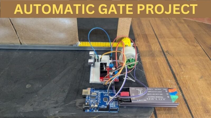
Hey guys, welcome back to the Techatronic. We have made a Project Automatic gate using DC motor. This is a simple programmable Project which use Arduino and ultrasonic sensor. the working of the project is very. simple whe any person comes in front of the sensor, which is placed at the gate front. so any person comes near the gate will open automatically. the gate mechanism uses the DC motor, which has high torque. so we are using gear motor. gears gives motor high torque. If you want to make this project please read full article i am going to share all the detail here and step by step instructions. you can attach this system with your other type of gate we have projects for the otheer type of gate. Automatic gate open & close. Now, lets start the making process.
Introduction
this is very simple and useful project which uses ultrasonic sesor , motor and Arduino by using C lagaueg which can make the program to operate this Project Automatic gate using DC motor. When you comes near the gate the sensor sense the object or person and gate will be close. this is very simple project. full video on how to make we have upload on the youtube. which we have given below.
An automatic gate system is commonly used in residential buildings, industries, parking areas, and restricted zones where controlled access is required. By using an Arduino microcontroller, the system can precisely control the movement of a DC motor that opens and closes the gate based on user commands or sensor inputs. The Arduino acts as the brain of the system, processing signals and controlling the motor through a motor driver circuit.
DC motors are preferred in this type of project because they are simple to control, cost-effective, and provide sufficient torque for gate movement. With the help of an H-bridge motor driver, the motor can rotate in both directions, allowing the gate to open and close smoothly. Additional components such as limit switches, IR sensors, or RF modules can be integrated to enhance safety and automation.
This project is an excellent example of how embedded systems can be applied to real-world problems. It helps beginners understand key concepts such as motor control, input-output interfacing, and Arduino programming. Moreover, the automatic gate system can be further upgraded with features like password control, RFID access, or mobile app operation, making it suitable for smart home and industrial applications.
Now, we are going to make this project. so , we will share the components list here.
Required Components for an Automatic gate using DC motor
| Components Name | Buy Link |
| Motor Driver L298N | BUY NOW |
| DC Geared Motor | BUY NOW |
| Breadboard | BUY NOW |
| Jumper wire | BUY NOW |
| Ultrasonic Sensor | BUY NOW |
| 12v Power Supply | BUY NOW |
| Arduino uno | BUY NOW |
| Gear Kit | BUY NOW |
You can buy the kit together here – BUY FULL KIT
Here we have given all the component required for this amazing project automatic Gate using DC motor. Now we need to assemble all the component. To assemble all the component we need a circuit diagram which can explain us how we can connect all the component together.
Circuit Diagram for an Automatic gate using DC motor
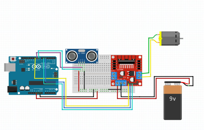
Circuit Diagram Explanation: Automatic Gate Using DC Motor & Arduino
This circuit shows an automatic gate system controlled by an Arduino Uno, a DC motor, an L298N motor driver, and an HC-SR04 ultrasonic sensor. The gate opens and closes automatically based on object detection.
1. Arduino Uno (Main Controller)
The Arduino Uno is the brain of the system.
It:
Reads distance data from the HC-SR04 ultrasonic sensor
Decides when to open or close the gate
Sends control signals to the L298N motor driver
Power Connections:
5V pin → Supplies power to the ultrasonic sensor
GND pin → Common ground for all components
2. Ultrasonic Sensor (HC-SR04)
The HC-SR04 sensor detects an object (vehicle/person) near the gate.
Pin Connections:
VCC → Arduino 5V
GND → Arduino GND
TRIG → Arduino digital pin (to send ultrasonic pulse)
ECHO → Arduino digital pin (to receive reflected signal)
Working:
The sensor sends ultrasonic waves
Measures the time taken for the echo to return
Arduino calculates distance
If distance is below a set value, the gate opens
3. L298N Motor Driver Module
The L298N is used to control the DC motor direction and speed, since Arduino cannot drive motors directly.
Connections to Arduino:
IN1 & IN2 → Control motor direction (open/close gate)
ENA → Enables motor (can be used with PWM for speed control)
GND → Connected to Arduino GND (common ground)
Power Connections:
12V input → Powered by the 9V battery
5V pin → Logic supply (depends on jumper configuration)
4. DC Motor (Gate Motor)
The DC motor represents the gate movement mechanism.
Connections:
Motor terminals → Connected to OUT1 & OUT2 of L298N
Working:
Motor rotates in one direction → Gate opens
Motor rotates in opposite direction → Gate closes
5. 9V Battery (Motor Power Supply)
Provides power to the L298N motor driver
Supplies sufficient current for the DC motor
Arduino and motor driver share a common ground
⚠️ Note: For real applications, a higher-current battery or power adapter is recommended instead of a 9V battery.
6. Breadboard (Power Distribution)
The breadboard is used to:
Distribute 5V and GND
Make neat and secure connections
Avoid soldering during testing
Overall Working of the Circuit
Ultrasonic sensor detects an object approaching the gate
Arduino calculates distance
If the object is within the preset range:
Arduino sends signals to L298N
DC motor rotates to open the gate
After a delay or when no object is detected:
Motor rotates in reverse
Gate closes automatically
After make conections wee need a code which cann help us to make our project Automatic gate using DC motor working.
Automatic gate using DC motor Code
// Ultrasonic sensor pins
#define trigPin 8
#define echoPin 9

// L298N motor pins
#define IN1 5
#define IN2 6
#define ENA 10

long duration;
int distance;

void setup() {
  pinMode(trigPin, OUTPUT);
  pinMode(echoPin, INPUT);

  pinMode(IN1, OUTPUT);
  pinMode(IN2, OUTPUT);
  pinMode(ENA, OUTPUT);

  stopMotor();

  Serial.begin(9600);
}

void loop() {
  distance = getDistance();

  Serial.print("Distance: ");
  Serial.print(distance);
  Serial.println(" cm");

  if (distance > 0 && distance <= 20) {

    // Rotate Clockwise
    digitalWrite(IN1, HIGH);
    digitalWrite(IN2, LOW);
    analogWrite(ENA, 200);   // speed (0–255)
    delay(1000);
stopMotor();
    delay(1000);
    // Rotate Anti-Clockwise
    digitalWrite(IN1, LOW);
    digitalWrite(IN2, HIGH);
    analogWrite(ENA, 200);
    delay(1000);

    stopMotor();
    delay(500); // small delay before next detection
  }
  else {
    stopMotor();
  }

  delay(200);
}

// Function to stop motor
void stopMotor() {
  digitalWrite(IN1, LOW);
  digitalWrite(IN2, LOW);
  analogWrite(ENA, 0);
}

// Function to measure distance
int getDistance() {
  digitalWrite(trigPin, LOW);
  delayMicroseconds(2);

  digitalWrite(trigPin, HIGH);
  delayMicroseconds(10);
  digitalWrite(trigPin, LOW);

  duration = pulseIn(echoPin, HIGH, 30000); // timeout 30ms
  if (duration == 0) return -1;

  return duration * 0.034 / 2;
}
1. Pin Definitions
// Ultrasonic sensor pins
#define trigPin 8
#define echoPin 9
trigPin → Sends ultrasonic pulses (TRIG pin of HC-SR04)
echoPin → Receives reflected pulse (ECHO pin)
Arduino pin 8 triggers the sensor, and pin 9 reads the echo.
// L298N motor pins
#define IN1 5
#define IN2 6
#define ENA 10
These pins control the DC motor through the L298N motor driver.
IN1 and IN2 → Control motor direction
ENA → Controls motor speed using PWM
🔹 2. Global Variables
long duration;
int distance;
duration → Stores time taken by ultrasonic wave to return
distance → Stores calculated distance in centimeters
🔹 3. setup() Function
void setup() {
This function runs only once when Arduino starts.
Pin Mode Configuration
pinMode(trigPin, OUTPUT);
pinMode(echoPin, INPUT);
TRIG → Output (send sound pulse)
ECHO → Input (receive pulse)
pinMode(IN1, OUTPUT);
pinMode(IN2, OUTPUT);
pinMode(ENA, OUTPUT);
Sets motor driver pins as outputs.
Stop Motor at Start
stopMotor();
Ensures the motor does not rotate when Arduino powers on
Prevents sudden movement
Serial Monitor
Serial.begin(9600);
Starts serial communication
Used to display distance values on Serial Monitor
🔹 4. loop() Function
void loop() {
This function runs continuously.
Measure Distance
distance = getDistance();
Calls the getDistance() function to calculate distance using ultrasonic sensor.
Print Distance
Serial.print(“Distance: “);
Serial.print(distance);
Serial.println(” cm”);
Displays the measured distance in centimeters.
🔹 5. Distance Condition Logic
if (distance > 0 && distance <= 20) {
Checks if an object is detected
Distance must be less than or equal to 20 cm
🔄 Motor Clockwise Rotation
digitalWrite(IN1, HIGH);
digitalWrite(IN2, LOW);
analogWrite(ENA, 200);
delay(2000);
Motor rotates clockwise
Speed ≈ 80% (200 out of 255)
Runs for 2 seconds
🔄 Motor Anti-Clockwise Rotation
digitalWrite(IN1, LOW);
digitalWrite(IN2, HIGH);
analogWrite(ENA, 200);
delay(2000);
Motor rotates anti-clockwise
Same speed
Runs for 2 seconds
🛑 Stop Motor
stopMotor();
delay(500);
Motor stops completely
Waits 0.5 seconds
Prevents sudden direction change
If No Object Detected
else {
stopMotor();
}
If distance > 20 cm or invalid
Motor remains OFF
Small Loop Delay
delay(200);
Reduces sensor noise
Prevents rapid re-triggering
🔹 6. stopMotor() Function
void stopMotor() {
digitalWrite(IN1, LOW);
digitalWrite(IN2, LOW);
analogWrite(ENA, 0);
}
What it does:
Stops motor direction
Sets motor speed to zero
Motor completely stops
🔹 7. getDistance() Function (Ultrasonic Logic)
Trigger Ultrasonic Pulse
digitalWrite(trigPin, LOW);
delayMicroseconds(2);
digitalWrite(trigPin, HIGH);
delayMicroseconds(10);
digitalWrite(trigPin, LOW);
Sends a 10µs ultrasonic pulse
Sensor emits sound waves
Measure Echo Time
duration = pulseIn(echoPin, HIGH, 30000);
Measures time taken for sound to return
Timeout after 30 ms (prevents freezing)
Handle No Echo
if (duration == 0) return -1;
If no object detected
Returns invalid distance
Calculate Distance
return duration * 0.034 / 2;
Speed of sound = 0.034 cm/µs
Divide by 2 (to-and-fro travel)
Result in centimeters
After completing the Circuit and Code. Now we need to upload the code into the Arduino.
Working of the project Automatic gate using DC motor
The working of this project is very simple there is an ultrasonic sensor which we have placed near the gate if someone comes in front of the gate the sensor will sense the person or object then it will send the command to the arduino. That there is something in front of the sensor the sensor continuously check the presence of any person or object. The ultrasonic sensor transmit the Ultrasonic waves to sense the object. the arduino react according to the signal. Arduino send command to the motor driver to rotate the motor anti clockwise for one second then stop for 1 second and again the motor rotate in clockwise direction for one second so this process make the kit open and close and study for one second. The duration of open and close gate can be differ as per your gear length. Here you can use any power supply from 9 volt to 12 volt directly to your l298 motor driver.