Table of Contents
Introduction
Hey geeks, hope you are doing fine. We are sure that you saw smoke and fire detectors fitted in buildings to enhance security.
We can call it smart as it automatically detects the smoke and sends an alert notification to our smart. hones. For controlling the MQ2 gas sensor we are using the Blynk app.
Please check how you can set up your Arduino IDE to upload the code in NodeMCU. You can also check our projects on IoT.
How Does it Work? /Working
- You have to provide your network’s SSID and PASSWORD in the code so that NodeMCU can able to send data over the internet. Also,
- you have to write the unique token in the code.
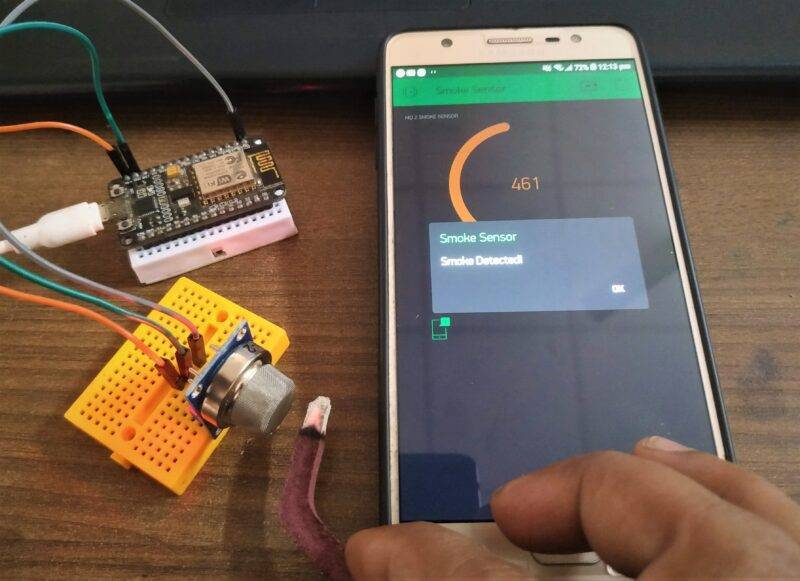
- This project will detect the smoke if present near it and alert you by sending the notification on your smartphone. Check the Blynk LPG detector made by us.
This article will make our own smart smoke detector with an MQ2 gas sensor and NodeMCU.
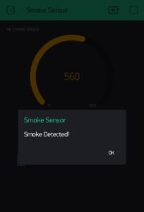
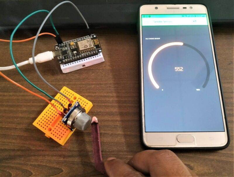
You can see the values taken by the MQ2 gas sensor on the gauge.
You can see the preview image of the project.

This is how the system works remotely.
Set up the Blynk app
Please install the Blynk IoT app on your smartphone. After installation opens the app.

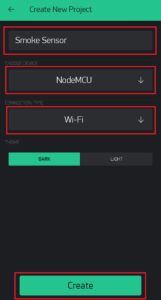
Create a new project
and name it what you want. Select the device as NodeMCU and the connection type as WiFi.

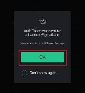
The app will ask you to provide your email address. A unique token id is sent by the app to your email address.
got token id

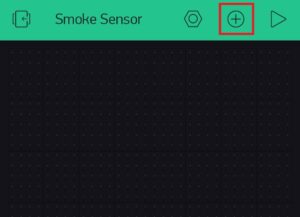
Open the widget box to add some graphical representations to your blynk page. Tap on the marked button to open the widgets menu.
make notification window
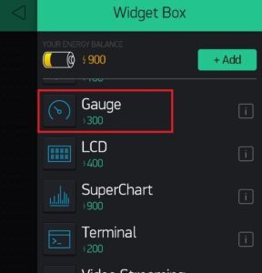
Now add a gauge and a notification widget from the menu. These widgets are given in the images below.

configure setting
Open the configuration settings of the gauge and set the pin value to the virtual-2 and set the range of the sensor. You can also provide the name of the gauge and set the color of it.

Now just upload the code and connect the NodeMCU to the internet. Once the NodeMCU is connected to the Blynk server you can see the data on the gauge as given in the image below.

Components Required
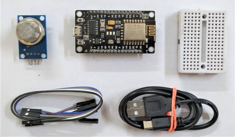
- NodeMCU esp8266 board
- USB cable for uploading the code
- MQ2 gas sensor
- breadboard and jumper wires
- Smartphone with a good internet connection
smart smoke detector Circuit Diagram
You can see here the clear image of the circuit diagram of the smoke detector.

Connection Table
| Nodemcu esp8266 | MQ-2 Smoke Sensor |
| VV, Vin | VCC |
| G, GND | GND |
| A0 Pin | A0 Pin |
Positive pin of the MQ2 gas sensor -> VIN pin of the NodeMCUMake the connections according to the given diagram.
Negative pin of the MQ2 gas sensor -> GND pin of the NodeMCU
Analog pin of the MQ2 gas sensor -> Analog-0 pin of the NodeMCU
smart smoke detector Code
NOTE: Please upload the code given below to the NodeMCU as it is. First install <ESP8266WiFi.h>, <SimpleTimer.h>, and <BlynkSimpleEsp8266.h> libraries to your IDE app. Check here how to install a zip library to Arduino IDE software.
 //TECHATRONIC.COM
 // BLYNK LIBRARY
 // https://github.com/blynkkk/blynk-library
 // ESP8266 LIBRARY
 // https://github.com/ekstrand/ESP8266wifi
 #include <ESP8266WiFi.h>
 #include <BlynkSimpleEsp8266.h>
 #include <SimpleTimer.h>
 #define BLYNK_PRINT Serial  // Comment this out to disable prints and save space
 char auth[] = "446r8LYJMJnXYrYqyEItR31Eh0jlH2m2"; //Enter Authentication code sent by Blynk
 char ssid[] = "DESKTOP"; //Enter WIFI Name
 char pass[] = "asdfghjkl"; //Enter WIFI Password
 SimpleTimer timer;
 int mq2 = A0; // smoke sensor is connected with the analog pin A0
 int data = 0;
 void setup()
 {
  Serial.begin(115200);
  Blynk.begin(auth, ssid, pass);
  timer.setInterval(1000L, getSendData);
 }
 void loop()
 {
  timer.run(); // Initiates SimpleTimer
  Blynk.run();
 }
 void getSendData()
 {
 data = analogRead(mq2);
  Blynk.virtualWrite(V2, data); // Blynk INPUT Connect V2 Pin
  if (data > 700 )
  {
   Blynk.notify("Smoke Detected!");
  }
 }
We hope that you understand the project well and now try to make your own. If you are facing any errors do inform us in the comments section below. You can check tutorials on Arduino and Rasberry Pi written by us.
Video sample
