This article will learn how to make a Remote Control Robot using Arduino and TSOP Sensor Module. In this project, we use a TSOP sensor for receiving the given signals from the IR remote control. If you are new to this field please do check out more projects on Arduino. Arduino is a microcontroller that uses ATmega328p IC for its functioning. There are many types of Arduino boards available in the market but we use Arduino UNO for this project. The Robot can move in different directions according to the buttons which we are pressing. For controlling the DC motors we use an L298n motor driver and provide a 12 volts supply to it. You can also check more Robots developed by using the Arduino. Follow the steps given below to complete the circuit and then upload the given Arduino code.

How Does it Work?
We use TSOP Sensor Module for receiving the IR signals which we give through pressing buttons of a remote. Our Robot can move in forward, backward, right, and left directions according to the given signals. We have to press the buttons of the remote to move the Robot in a particular direction. We use four LEDs of different colors which will go on as the robot moves in different directions. it works as a Bluetooth control robot. If the Robot will move forward the LED on pin 3 will glow, the same for the backward LED on pin 4 will glow, the LED on pin 5 will glow if the robot moves in the right, and the LED on pin 6 will glow if the robot moves in left. The Robot keeps moving until we press the stop button on the remote. All the LEDs reset to off. In this way, the Robot moves.

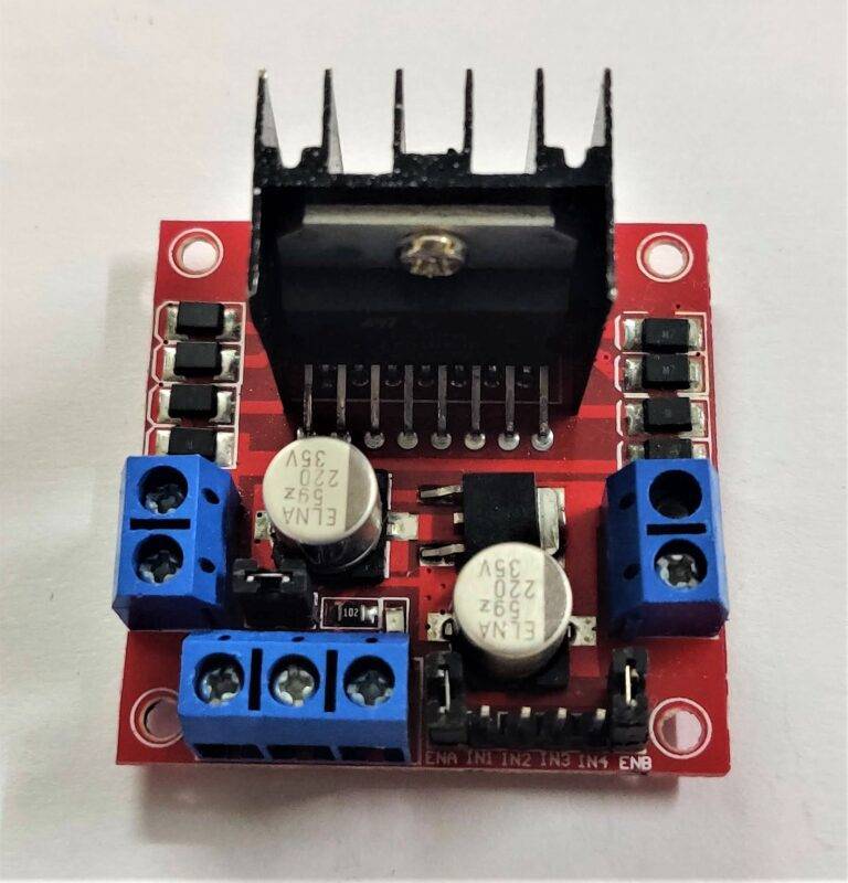
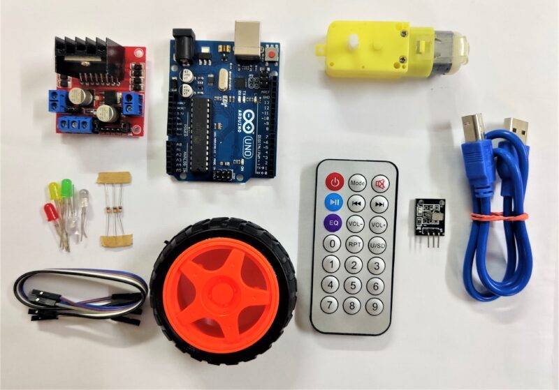
Components Required for tsop 1738 robot
- Arduino UNO
- USB Cable for Uploading the Code
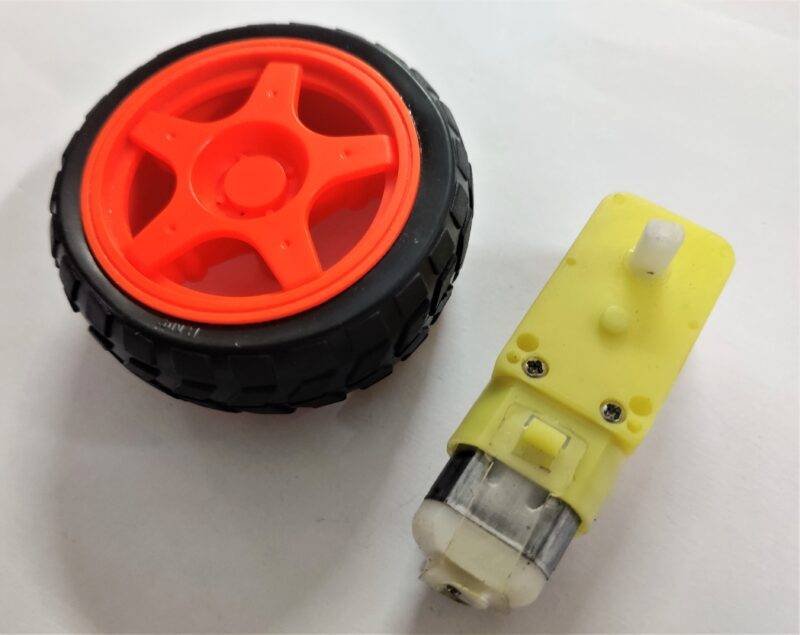
- Four DC Motors with Wheels
- Jumper Wires
- Jumper Wires
- Breadboard
- Switch
- TSOP Sensor Module
- Resistor 220-ohm
- LEDs of Four Different Colors
| Arduino UNO | BUY LINK |
| USB Cable for Uploading the Code | BUY LINK |
| 4-BO Motors | BUY LINK |
| L298n Motor Driver | BUY LINK |
| Jumper Wires | BUY LINK |
| 4-Wheels | BUY LINK |
| Breadboard | BUY LINK |
| Switch | BUY LINK |
| TSOP Sensor Module | BUY LINK |
| Resistor 220-ohm | BUY LINK |
| LEDs of Four Different Colors | BUY LINK |
Circuit Diagram of the Robot

connect table for tsop 1738 robot
| Arduino UNO | L298N Motor Driver | ||||
| 9 Pin | IN 1 | ||||
| 10 Pin | IN 2 | ||||
| 11 Pin | IN 3 | ||||
| 12 Pin | IN 4 | ||||
| Arduino UNO | Tsop TV Remote Sensor | ||||
| ( +5V ) | + VCC | ||||
| GND | – GND | ||||
| 8 Pin | S Signal | ||||
| Arduino | 9 & 12 V Battery | Switch | Motor Driver | ||
| Positive | Terminal 1 | ||||
| Terminal 2 | +12 Volt | ||||
| +5V | +5 Volt | ||||
| GND | Negative | GND | |||
| Arduino | Led R | Led G | Led B | Led Y | 220 Ohm Resistance |
| D3 Pin | Anode | ||||
| D4 Pin | Anode | ||||
| D5 Pin | Anode | ||||
| D6 Pin | Anode | ||||
| GND | Terminal 1 | ||||
| Cathode | Cathode | Cathode | Cathode | Terminal 2 | |
| Motor 1, 2 | Motor 3, 4 | L298N Motor Driver | |||
| Terminal 1 | Terminal 1 Output | ||||
| Terminal 2 | Terminal 2 Output | ||||
| Terminal 1 | Terminal 3 Output | ||||
| Terminal 2 | Terminal 4 Output |
Connect the DC motors to the L298n driver as pair of two on each side as shown above. Attach the 5 volts and GND pin of the driver to the 5 volts and GND pin of the Arduino and 12 volts to the external power supply. Join the same GND pin of the Arduino to the negative of the external power supply. Connect the VCC and GND of the TSOP sensor module to the positive and negative terminal of the Arduino and the out pin to the digital 8 of the Arduino. Connect the digital 9, 10, 11, 12 pins of the Arduino to the L298n motor driver as shown. Attach the positive leg of all the LEDs to the digital 3, 4, 5, 6 pins of the Arduino through 220-ohm resistors and all the negative legs to the GND terminal. After completing the circuit upload the code given below.
Arduino Code for the Robot using tsop 1738
NOTE: Upload the code given below to the Arduino. You have to install <IRremote.h> in your IDE application.
 #include <IRremote.h>
 int RECV_PIN = 11;
 int val ;
 IRrecv irrecv(RECV_PIN);
 decode_results results;
 void setup()
 {
  Serial.begin(9600);
  Serial.println("Enabling IRin");
  irrecv.enableIRIn();
  Serial.println("Enabled IRin");
  pinMode(3,OUTPUT); // LED 1
  pinMode(4,OUTPUT); // LED 2
  pinMode(5,OUTPUT); // LED 3
  pinMode(6,OUTPUT); // LED 4
  pinMode(9,OUTPUT); // MOTOR 1
  pinMode(10,OUTPUT); // MOTOR 2
  pinMode(11,OUTPUT); // MOTOR 3
  pinMode(12,OUTPUT); // MOTOR 4
 }
 void loop()
 {
  if (irrecv.decode(&results))
  {
   val = results.value, HEX ;
   Serial.println(val);
   irrecv.resume(); // Receive the next value
  // FORWARD DIRECTION
   if(val == 18615 )
  {
   digitalWrite(3,HIGH);
   digitalWrite(4,LOW);
   digitalWrite(5,LOW);
   digitalWrite(6,LOW);
   digitalWrite(9,HIGH);
   digitalWrite(10,LOW);
   digitalWrite(11,LOW);
   digitalWrite(12,HIGH);
  }
 // BACKWARD DIRECTION
   if(val == 22695 )
  {
    digitalWrite(3,LOW);
   digitalWrite(4,HIGH);
   digitalWrite(5,LOW);
   digitalWrite(6,LOW);
   digitalWrite(9,LOW);
   digitalWrite(10,HIGH);
   digitalWrite(11,HIGH);
   digitalWrite(12,LOW);
  }
  // RIGHT DIRECTION
   if(val == 30855 )
  {
   digitalWrite(3,LOW);
   digitalWrite(4,LOW);
   digitalWrite(5,HIGH);
   digitalWrite(6,LOW);
   digitalWrite(9,LOW);
   digitalWrite(10,HIGH);
   digitalWrite(11,LOW);
   digitalWrite(12,HIGH);
  }
  // LEFT DIRECTION
   if(val == -32641 )
  {
   digitalWrite(3,LOW);
   digitalWrite(4,LOW);
   digitalWrite(5,LOW);
   digitalWrite(6,HIGH);
   digitalWrite(9,HIGH);
   digitalWrite(10,LOW);
   digitalWrite(11,HIGH);
   digitalWrite(12,LOW);
  }
 // STOP
   if(val == 17369 )
  {
   digitalWrite(3,LOW);
   digitalWrite(4,LOW);
   digitalWrite(5,LOW);
   digitalWrite(6,LOW);
   digitalWrite(9,LOW);
   digitalWrite(10,LOW);
   digitalWrite(11,LOW);
   digitalWrite(12,LOW);
  }
  delay(10);
 }
 }
The Remote Control Robot using tsop 1738 Looks Like

Hope you understand the project well. If you are facing any errors do inform us in the comments section below. Check out more Arduino Tutorials.
HAPPY LEARNING!


