
We will learn about the 433MHz RF Module and how to interface it with an Arduino in today’s article. We will also study the operation of this module and the process of wireless communication. Lastly, we will discover how to send and receive data packets wirelessly using this module with an Arduino.
Table of Contents
Components Required For RF Module
You need the following components for this example:
Features of RF Transmitter and Receiver:
- Receiver frequency: 433MHz
- Receiver typical sensitivity: 105Dbm
- Low power consumption
- Receiver current supply: 3.5mA
- Transmitter frequency range between 433.92MHz
- Receiver operating voltage: 5V
- Transmitter supply voltage between 3V~6V
- Transmitter output power range between 4~12Dbm
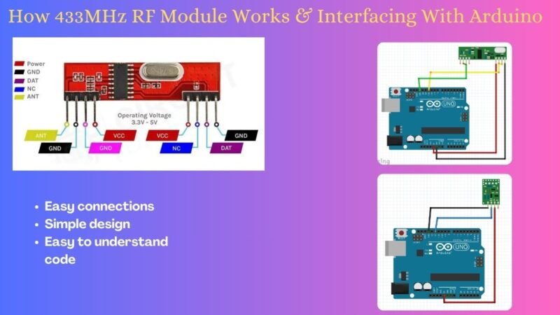
433MHz RF Module
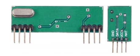
This module therefore appears exactly as it does in the figure above. additionally available in a range of bundles. All these modules accomplish the same thing, though, in essence. You can purchase any of these modules. The transmitter section is tiny, with only four pins, while the receiver section has eight pins and is slightly larger.
To send and receive data, an RF transceiver module needs a transmitter and receiver. It always works in pairs. A transmitter can only send data, and a receiver can only receive it. Data can only be sent from one end to the other.
As seen above, the transmitter module is made up of three pins: ground, Din, and Vcc. The input voltage range for the Vcc pin is wide, ranging from 3V to 12V. During transmission, the transmitter’s minimum current consumption is 9 mA, and it can reach up to 40 mA.
The data pin used to transmit the signal is located in the center. This signal was transmitted on air at a frequency of 433MHz after being modulated using the ASK. As seen above, the RF receiver module has four pins: Vcc, Dout, Linear Out, and Ground.
It is necessary to use a regulated 5V supply to power the VCC pin. This module has an operating current of less than 5.5mA. To receive the 433MHz signal from the air, the pins Dout and Linear out are shorted together. Click here to read more.
Transmitter Section
This little module is the transmitter. The main part of the module is the SAW resonator, which is tuned for 433 MHz operations. There’s a switching transistor and a couple of passive components.
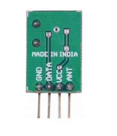
When a logic HIGH is applied to the DATA input, the oscillator generates a continuous RF output carrier wave at 433 MHz. When the logic LOW setting is applied to the DATA input, the oscillator stops working. Amplitude shift keying is the name of this technique, which is discussed below.
Receiver Section

This one is a receiving module. it consists of a few OP Amps to increase the carrier wave received from the transmitter and an RF-tuned circuit. The phase Lock Loop (PLL), which enables the decoder to “lock” onto a stream of digital bits for enhanced output decoding and noise immunity, receives the boosted signal next.
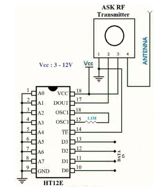
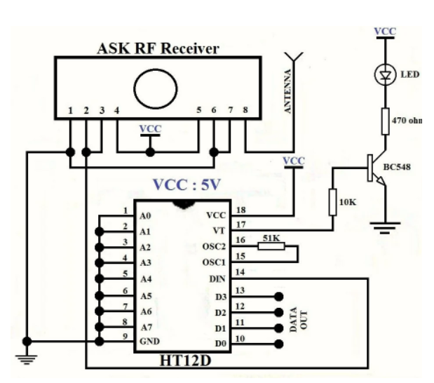
Why Encoders and Decoders are Necessary?
The RF modules can function without the encoder and decoder modules. As previously mentioned, use the appropriate voltage to turn on both modules. But there’s a big problem with this strategy. On the sender and recipient sides, respectively, only one output and one button are permitted.
Therefore, in order to have more inputs and outputs, the encoder and decoder modules are required. The HT12D and HT12E modules are the 4-data bit encoder and decoder modules. As a result, the possible combinations of inputs and outputs are 16*2^4 = 16. The input power supply range for these 18-pin integrated circuits is 3 to 12 volts.
As mentioned, they have four data bits and eight address bits. For the encoder and decoder to function together, the eight address bits must be set to the same value on both devices.
Applications of RF Module
- Small-range wireless network
- Wireless meter reading
- Access control systems
- Wireless home security systems
- Area paging
- Industrial data acquisition system
- Radio tags reading
- RF contactless smart cards
- Wireless data terminals
- Wireless fire protection systems
- Biological signal acquisition
- Hydrological and meteorological monitoring
- Robot remote control
- Wireless data transmissions
- Digital video/audio transmission
- Digital home automation, such as remote light/switch
- Industrial remote control, telemetry and remote sensing
Interfacing 433Mhz RF Module with Arduino
Let’s look at how to interface a 433MHz radio module with an Arduino. Since we will be sending data between the two Arduino boards, we will also need two breadboards and a few jumper wires. Every section of the RF module has an antenna.
Even though the antenna should be 69 cm tall, having an antenna that long is not practical. As a result, any wired antenna that is roughly 17 cm long will function.
Transmitter Wiring
The transmitter’s wiring is straightforward. There are just three connections on it. Attach the Arduino’s GND pin to ground and VCC pin to the 5V pin.

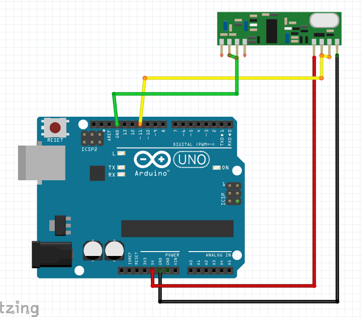
Receiver Wiring
The receiver’s wiring is simple too, same like transmitter. There are just three connections to be made once more. Attach the Arduino’s GND pin to ground and VCC pin to the 5V pin. As indicated in the figure, digital pin 11 should be connected to either of the middle two Data-Out pins.
Code for 433MHz RF Module
You must install a library called a Radiohead library before you can upload the code. A library called Radiohead enables straightforward data transfer between Arduino boards. Because of its extreme adaptability, it can be used to power a wide range of radio communications equipment, including our 433MHz modules.
Transmitter Code
#include <RH_ASK.h> // Include RadioHead Amplitude Shift Keying Library
#include <SPI.h> // Include dependant SPI Library

// Create Amplitude Shift Keying Object
RH_ASK rf_driver;

void setup()
{
// Initialize ASK Object
rf_driver.init();
// Setup Serial Monitor
Serial.begin(9600);
}

void loop()
{
const char *msg = "Hello World";
rf_driver.send((uint8_t *)msg, strlen(msg));
rf_driver.waitPacketSent();
{
// Message Transmitted
Serial.println("Message Transmitted: ");
delay(1000);
}
}
Receiver Code
#include <RH_ASK.h> // Include RadioHead Amplitude Shift Keying Library
#include <SPI.h> // Include dependant SPI Library
// Create Amplitude Shift Keying Object
RH_ASK rf_driver;
void setup()
{
// Initialize ASK Object
rf_driver.init();
// Setup Serial Monitor
Serial.begin(9600);
}
void loop()
{
// Set buffer to size of expected message
uint8_t buf[11];
uint8_t buflen = sizeof(buf);
// Check if received packet is correct size
if (rf_driver.recv(buf, &buflen))
{
// Message received with valid che-cksum
Serial.print("Message Received: ");
Serial.println((char*)buf);
}
}FAQ(Frequently Asked Questions)
Q.1) How to download library?
Ans. Open Arduino IDE and click on sketch > click Include libraries > click Manage library > search RadioHead. Click install.
Q.2) Can it be used in long range?
Ans. No, 433MHz RF Module can not be used for long range, it can only be used for short ranges.