
Hello guys, welcome back to Techatronic. Do you know how a water level indicator project using the ic 555 circuit works?
Well in this article we are going to make it using a 555 timer ic. Generally, water tanks don’t equip with a water overflow mechanism and it leads to a lot of water wastage.
If you turn on the pump and forgot to turn it off after some time then this circuit is for you. All the details are shared below. You can also read articles on Arduino and IoT written by us
So without wasting any more time let’s first understand the working of this circuit.

Table of Contents
water level indicator working
- In this project, we are making a water level indicator project using ic 555 timer which can be helpful in detecting the overflow of water in water tanks.
- You just have to complete the circuit which is given below and places the wires inside the tank at different positions. When you start the water pump to fill the water tank the circuit will activate automatically.
- It will check if the level of the water inside the tank is full or not by means of wires that we place inside the tank. If the water level is low or moderate the pump will continue working and
- when the water level is full the circuit will cut the supply of the water pump and turn it off. You can also check the 555 delay timer with On/Off made by us.
Components Required
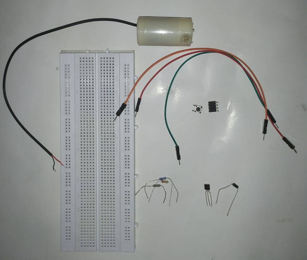
| 555 timer ic | BUY LINK |
| Two 1M resistors | BUY LINK |
| 100-ohm resistor | BUY LINK |
| 1N4007 diode | BUY LINK |
| BC547 transistor | BUY LINK |
| Water pump | BUY LINK |
| jumper wire | BUY LINK |
| breadboard | BUY LINK |
Circuit for Water Level Controller Using ic 555

Take a 555 timer ic and place it on the breadboard.
- Connect pins 4 and 8 together.
- Connect the positive and negative rails of the breadboard with the positive and negative terminals of the power supply.
- Now join pin 1 with the negative rail and pin 8 with the positive rail in this tank level monitoring system.
- Join pin 6 of the ic with the negative rail via a 1M resistor.
- Similarly, join pin 2 of the ic with the negative rail via a 1M resistor. Connect pin 3 with the base pin of the transistor via a 100-ohm resistor.
- Take a diode and connect its positive leg with the pin.
- Join the negative leg of the diode with the positive rail of the breadboard.
- Connect the emitter pin of the transistor with the negative rail.
- Now take a water pump and join one wire with the collector pin of the transistor and the other wire with the positive rail.
Extend the wires from pins 6 and 2 and put them in the water tank along with the positive supply wire.
Tie the wire from pin 6 on the top and wire from pin 2 on the bottom. Your circuit is complete now.
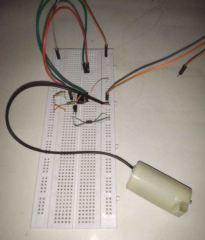
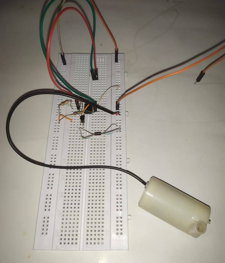
water tank level monitor Circuit
We hope that you liked water level controller using ic 555 and understand completely how 555 ic is functioning in this water level indicator project.
If you have any suggestions or doubts related to this project then feel free to use the comments section which is given below. Also, do check out more projects on Arduino and Raspberry Pi.
Thanks for reading.
Latest 555 timer projects
555 delay timer with ON/OFF | 555 timer delay off circuit
LED Brightness Control using Potentiometer| LED Fade | 555 timer project