

Hello everyone, welcome back to Techatronic. Today we are going to make an interesting project called ‘Voice Controlled LED Using Google Assistant’. This project may sound like an advance programming project but it is not. This is very simple to make and easy to understand code.
We made a DIY demonstration of how to use an ESP32, Sinric Pro, and Google Assistant to build a voice-activated LED controller in this article.
Envision a smart, futuristic home. A voice greets you as soon as you walk through the front door and updates you on the latest events and situation in your home. Subsequently, you react to create a particular atmosphere, and the lights and music adjust appropriately.
In these kinds of scenarios, voice control is still a long way from being used regularly, even if it is feasible. Still, creating a device that can be activated by voice is a start in that direction.
Table of Contents
Components Required for Voice Controlled LED Using Google Assistant.
ESP32
The ESP32 is a chip that gives embedded devices, or Internet of Things devices, Wi-Fi and (in certain models) Bluetooth connectivity. Although ESP32 is only the chip, the manufacturer also frequently refers to the development boards and modules that contain this chip as “ESP32.”
A single core Tensilica Xtensa LX6 microprocessor powered the original ESP32 chip. With a clock rate of more than 240 MHz, the processor processed data at a comparatively fast pace.There are now more recent models available, such as the ESP32-C and -S series, which have one or two cores.
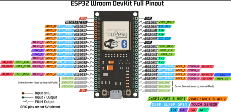
These two series also use a Risc-V CPU model in place of Xtensa. Risc-V resembles the widely used and supported ARM architecture despite being open source and easy to use. More precisely, ARM and Risc-V are well supported by GNU compilers; however, Xtensa needed more work and support in order to be compatible with them.
The ESP32 is primarily used in wearable technology, mobile devices, and Internet of Things applications such as Nabto Edge. Furthermore, the ESP32 has distinguished itself as the greatest chip available for IoT developers and enthusiasts since Mongoose OS unveiled an ESP32 IoT Starter Kit. Its resources and capabilities have grown significantly over the last four years, and it can be used for commercial IoT.
How voice controlled LED using Google Assistant works?
Well, we don’t need to worry about this because there are some applications which would work behind the scenes to make this work, we only need to configure them according to our needs. We would write the code which is provided below and configure two applications to make the code run. To make little bit of advanced project, click here.
Circuit Diagram of Voice Controlled LED Using Google Assistant
Follow this circuit diagram to make the connections. You can make this circuit on the breadboard with the help of jumper wires.

Code for Voice Controlled LED Using Google Assistant
Before you upload the code, make sure you have downloaded these libraries. The libraries are-
- Sinric Pro
- ArduinoJson
- WebSockets
//#define ENABLE_DEBUG
#ifdef ENABLE_DEBUG
#define DEBUG_ESP_PORT Serial
#define NODEBUG_WEBSOCKETS
#define NDEBUG
#endif
#include <Arduino.h>
#include <WiFi.h>
#include "SinricPro.h"
#include "SinricProSwitch.h"
#include <map>
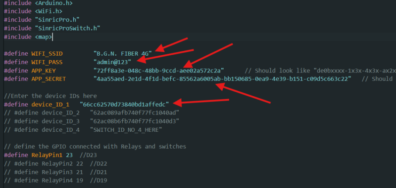
#define WIFI_SSID "B.G.N. FIBER 4G"
#define WIFI_PASS "admin@123"
#define APP_KEY "72ff8a3e-048c-48bb-9ccd-aee02a572c2a" // Should look like "de0bxxxx-1x3x-4x3x-ax2x-5dabxxxxxxxx"
#define APP_SECRET "4aa55aed-2e1d-4f1d-befc-85562a6005ab-bb150685-0ea9-4e39-b151-c09d5c663c22" // Should look like "5f36xxxx-x3x7-4x3x-xexe-e86724a9xxxx-4c4axxxx-3x3x-x5xe-x9x3-333d65xxxxxx"
//Enter the device IDs here
#define device_ID_1 "66cc62570d73840bd1affedc"
// #define device_ID_2 "62ac089afb740f77fc1040ad"
// #define device_ID_3 "62ac08b6fb740f77fc1040d3"
// #define device_ID_4 "SWITCH_ID_NO_4_HERE"
// define the GPIO connected with Relays and switches
#define RelayPin1 23 //D23
// #define RelayPin2 22 //D22
// #define RelayPin3 21 //D21
// #define RelayPin4 19 //D19
#define SwitchPin1 13 //D13
// #define SwitchPin2 12 //D12
// #define SwitchPin3 14 //D14
// #define SwitchPin4 27 //D27
#define wifiLed 2 //D2
// comment the following line if you use a toggle switches instead of tactile buttons
//#define TACTILE_BUTTON 1
#define BAUD_RATE 9600
#define DEBOUNCE_TIME 250
typedef struct { // struct for the std::map below
int relayPIN;
int flipSwitchPIN;
} deviceConfig_t;
// this is the main configuration
// please put in your deviceId, the PIN for Relay and PIN for flipSwitch
// this can be up to N devices...depending on how much pin's available on your device ;)
// right now we have 4 devicesIds going to 4 relays and 4 flip switches to switch the relay manually
std::map<String, deviceConfig_t> devices = {
//{deviceId, {relayPIN, flipSwitchPIN}}
{device_ID_1, { RelayPin1, SwitchPin1 }},
{device_ID_2, { RelayPin2, SwitchPin2 }},
{device_ID_3, { RelayPin3, SwitchPin3 }},
{device_ID_4, { RelayPin4, SwitchPin4 }}
};
typedef struct { // struct for the std::map below
String deviceId;
bool lastFlipSwitchState;
unsigned long lastFlipSwitchChange;
} flipSwitchConfig_t;
std::map<int, flipSwitchConfig_t> flipSwitches; // this map is used to map flipSwitch PINs to deviceId and handling debounce and last flipSwitch state checks
// it will be setup in "setupFlipSwitches" function, using informations from devices map
void setupRelays() {
for (auto &device : devices) { // for each device (relay, flipSwitch combination)
int relayPIN = device.second.relayPIN; // get the relay pin
pinMode(relayPIN, OUTPUT); // set relay pin to OUTPUT
digitalWrite(relayPIN, HIGH);
}
}
void setupFlipSwitches() {
for (auto &device : devices) { // for each device (relay / flipSwitch combination)
flipSwitchConfig_t flipSwitchConfig; // create a new flipSwitch configuration
flipSwitchConfig.deviceId = device.first; // set the deviceId
flipSwitchConfig.lastFlipSwitchChange = 0; // set debounce time
flipSwitchConfig.lastFlipSwitchState = true; // set lastFlipSwitchState to false (LOW)--
int flipSwitchPIN = device.second.flipSwitchPIN; // get the flipSwitchPIN
flipSwitches[flipSwitchPIN] = flipSwitchConfig; // save the flipSwitch config to flipSwitches map
pinMode(flipSwitchPIN, INPUT_PULLUP); // set the flipSwitch pin to INPUT
}
}
bool onPowerState(String deviceId, bool &state)
{
Serial.printf("%s: %s\r\n", deviceId.c_str(), state ? "on" : "off");
int relayPIN = devices[deviceId].relayPIN; // get the relay pin for corresponding device
digitalWrite(relayPIN, !state); // set the new relay state
return true;
}
void handleFlipSwitches() {
unsigned long actualMillis = millis(); // get actual millis
for (auto &flipSwitch : flipSwitches) { // for each flipSwitch in flipSwitches map
unsigned long lastFlipSwitchChange = flipSwitch.second.lastFlipSwitchChange; // get the timestamp when flipSwitch was pressed last time (used to debounce / limit events)
if (actualMillis - lastFlipSwitchChange > DEBOUNCE_TIME) { // if time is > debounce time...
int flipSwitchPIN = flipSwitch.first; // get the flipSwitch pin from configuration
bool lastFlipSwitchState = flipSwitch.second.lastFlipSwitchState; // get the lastFlipSwitchState
bool flipSwitchState = digitalRead(flipSwitchPIN); // read the current flipSwitch state
if (flipSwitchState != lastFlipSwitchState) { // if the flipSwitchState has changed...
#ifdef TACTILE_BUTTON
if (flipSwitchState) { // if the tactile button is pressed
#endif
flipSwitch.second.lastFlipSwitchChange = actualMillis; // update lastFlipSwitchChange time
String deviceId = flipSwitch.second.deviceId; // get the deviceId from config
int relayPIN = devices[deviceId].relayPIN; // get the relayPIN from config
bool newRelayState = !digitalRead(relayPIN); // set the new relay State
digitalWrite(relayPIN, newRelayState); // set the trelay to the new state
SinricProSwitch &mySwitch = SinricPro[deviceId]; // get Switch device from SinricPro
mySwitch.sendPowerStateEvent(!newRelayState); // send the event
#ifdef TACTILE_BUTTON
}
#endif
flipSwitch.second.lastFlipSwitchState = flipSwitchState; // update lastFlipSwitchState
}
}
}
}
void setupWiFi()
{
Serial.printf("\r\n[Wifi]: Connecting");
WiFi.begin(WIFI_SSID, WIFI_PASS);
while (WiFi.status() != WL_CONNECTED)
{
Serial.printf(".");
delay(250);
}
digitalWrite(wifiLed, HIGH);
Serial.printf("connected!\r\n[WiFi]: IP-Address is %s\r\n", WiFi.localIP().toString().c_str());
}
void setupSinricPro()
{
for (auto &device : devices)
{
const char *deviceId = device.first.c_str();
SinricProSwitch &mySwitch = SinricPro[deviceId];
mySwitch.onPowerState(onPowerState);
}
SinricPro.begin(APP_KEY, APP_SECRET);
SinricPro.restoreDeviceStates(true);
}
void setup()
{
Serial.begin(BAUD_RATE);
pinMode(wifiLed, OUTPUT);
digitalWrite(wifiLed, LOW);
setupRelays();
setupFlipSwitches();
setupWiFi();
setupSinricPro();
}
void loop()
{
SinricPro.handle();
handleFlipSwitches();
}Server Configuration
First, visit https://sinric.pro/
You have to create an account in Snric Pro.
After logging in, you will be given an APP KEY and APP SECRET for the account, which will be needed in the code further.
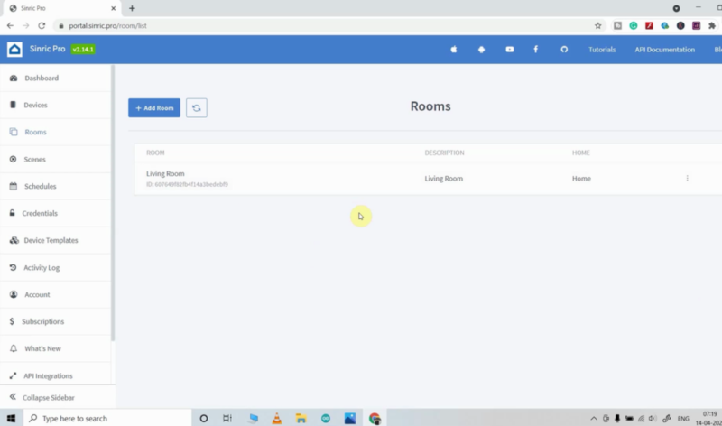

Next, add a room and label it (living room, for example).
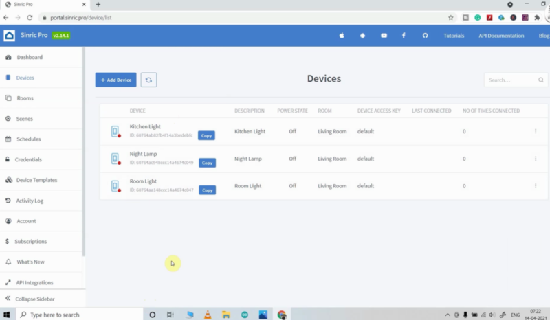
Next, add each device individually, giving it a nickname.
Sinric will provide each device with a unique device ID. I can add up to three devices for free because I have a free Sinric Pro account.
Now, enter the WiFi Credentials which you have copied above in sinric website-
Google Home App Setup
Download the Google Home App from play store and follow the give steps to create Home.
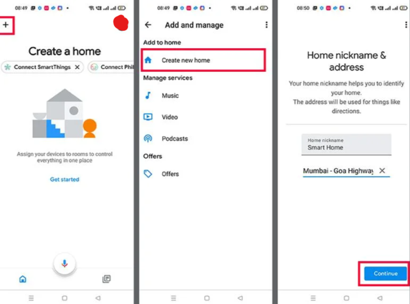
- Press the “+” icon.
- Press the Create new home.
- Enter the Home nickname and address.
- Now click on Continue.
Home is created. Now tap on the “+” icon again to add devices.
Connect Sinric Pro With Google Home App
Now, the next step is to connect the Sincric pro with the Google Home app to make it function properly, otherwise it would not work.
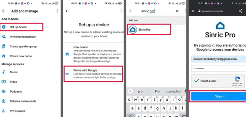
- Press “+” icon, then select Set up device.
- Press “Works with Google“.
- Search “Sinric Pro“, then select “Sinric Pro“.
- Enter the email id and password which you used to make account in the Sinric pro.
- Then tap on Sign in.
As a result, Google Home Account will have access to all of Sinric Pro’s devices.
Now, you are good to go to give your voice command to Google Assistant and it will turn ON and OFF your LED. And you can also turn ON an OFF the LED with the help of virtual buttons give to you in your Google Home app.
FAQ(Frequently Asked Questions)
Q1.) What are the libraries which I need to download to make this code run?
- <Arduino.h>
- <WiFi.h>
- “SinricPro.h”
- “SinricProSwitch.h”
- <map>
Q2.) How does ESP32 works?
Ans. Click here to know about ESP32.
Q.2) LED turning ON and OFF with the button but not activating with voice command. Why?
Ans. Go to your phone setting and turn on google assistant.
I have assembled the whole circuit on a breadboard. As you know breadboard assembly is not effective for this type of project. So, PCBWay offers Rapid PCB Prototyping for Your Research Work. I personally, recommend PCBWay because you can get your first-try boards right in 24 hours!

The prototyping stage is the most critical period of time for engineers, students, and hobbyists. PCBWay not only makes your boards quick but also makes your job right as well as cost-effective. This greatly reduces your cost and shortens the time for developing your electronic
PCBWay can provide 2 Layer PCBs to highly advanced HDI and flex boards. Even though the PCBs they produce differ a lot regarding functionality and areas of use. I am impressed with the quality of the boards, the delivery time, and the cost-effectiveness