

Table of Contents
Introduction
Hey geeks, welcome back to Techatronic. In this article, we are going to control a robot arm using the Blynk application with the help of the nodemcu board. You can control the movement of this robot arm using your smartphone. You just need good internet connectivity for its functioning. When you touch the joystick and move in different directions then the robot arm will also move accordingly.
This joystick will work as a wireless remote for the robot arm that we made. These kinds of robot arms will use in many types of projects for various purposes. You can also check our articles on Arduino and IoT. Make the circuit according to the circuit diagram and then upload the code to the nodemcu.
Description
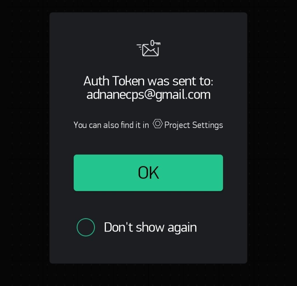
First of all, you need to download and install the Blynk application from any app store on your smartphone. Then sign in to it. It will ask for your email address so that you will get your unique token number.
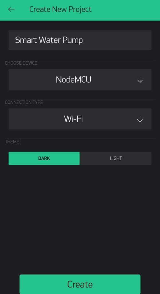
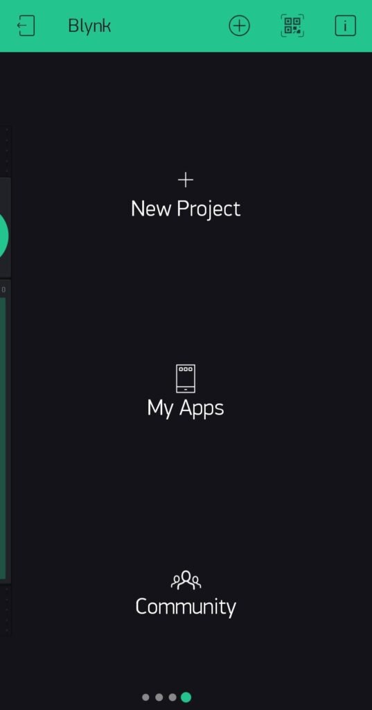
Then create a new project and set the device as nodemcu.
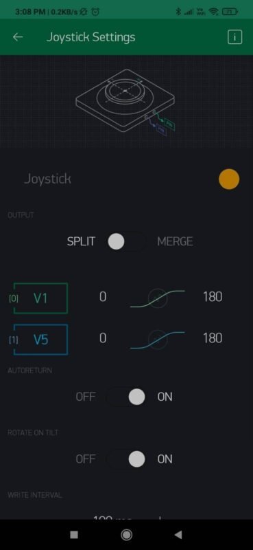
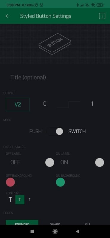
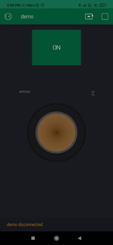
Then open the widgets section and select the joystick. Make the settings as shown in the image given below. Then add a button and proceed further. Run the simulation on the Blynk app and wait for the connection between the smartphone and the nodemcu. Make sure to add the SSID and password in the code so that nodemcu can access the internet.
Components Required
| ESP8266 nodemcu | BUY LINK |
| LED | BUY LINK |
| 2 Servo motors | BUY LINK |
| Jumper wires | BUY LINK |
| breadboard | BUY LINK |
| USB cable for uploading the code | BUY LINK |
Circuit Diagram
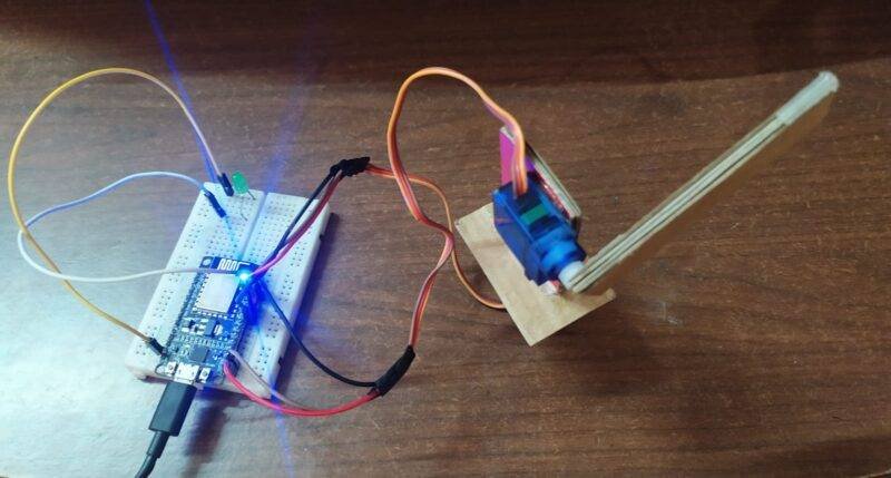
- Take two servo motors and place them one over the other as shown in the project image.
- You can use a cardboard piece for joining purposes.
- Then connect the positive supply wire of the servo motor with the 3 volt pin of the nodemcu. Join the negative supply wire of the servo motor with the GND pin of the nodemcu.
- For the second servo motor connect the negative supply wire with the GND pin of the nodemcu and Join the positive supply wire of the motor with the 3 volt pin of the nodemcu.
- Connect the signal wire of the first servo motor with the digital-2 pin of the nodemcu.
- Join the signal wire of the second servo motor with the digital-4 pin of the nodemcu.
- Then take an LED and connect its negative leg with the GND pin of the nodemcu.
- Join the positive leg of the LED with the digital-1 pin of the nodemcu. Your circuit is complete now.
Code for the
NOTE: Please upload the code to the nodemcu. You have to install <ESP8266WiFi.h>, <BlynkSimpleEsp8266.h> libraries to the Arduino IDE. Check here how to add a zip library to the software.
//Techatronic.com
#define BLYNK_PRINT Serial
#include <ESP8266WiFi.h>
#include <BlynkSimpleEsp8266.h>
#include <Servo.h>

Servo motor1;
Servo motor2;
int LED = 5;   //NodeMCU D1 pin

char auth[] = "xxxxxxxxxxxxxxxxxxxxxxxxxxxxxx"; //  your auth code
char ssid[] = "  ";  // ssid name
char pass[] = "  "; // ssid password

void setup()
{
  Serial.begin(9600);
  Blynk.begin(auth, ssid, pass);

  motor1.attach(2); // NodeMCU D4 pin
  motor2.attach(4); // NodeMCU D2 pin
  pinMode(LED, OUTPUT);
 }
void loop()
{
  Blynk.run();
}
 BLYNK_WRITE(V5)
{
   motor2.write(param.asInt());
}
 BLYNK_WRITE(V1)
{
   motor1.write(param.asInt());
}
BLYNK_WRITE(V2)
{
   if(param.asInt()== HIGH)
   {
    digitalWrite(LED,HIGH);
   }
   else
   {
    digitalWrite(LED,LOW);
   }
}
We hope that you understand the working of this project entirely and now please try to make it on your own for better understanding. If you have any doubts about this project, do let us know in the comments section given below. You can also check out more articles on Arduino and Raspberry Pi written by us.
Thanks for reading.