Hey guys, welcome back to Techatronic. Do you want to make a VU meter using basic electronic components? If so then you are at the right place. In this article, we are going to discuss the procedure to make an RGB VU meter using ic LM3915. This ic is an 18 pin ic having 9 pins on each side. You can identify the pins using the notch mark given on the top of the ic or you can also see the datasheet of the ic. We have also made various amazing projects on Arduino and IoT, you can also check them.
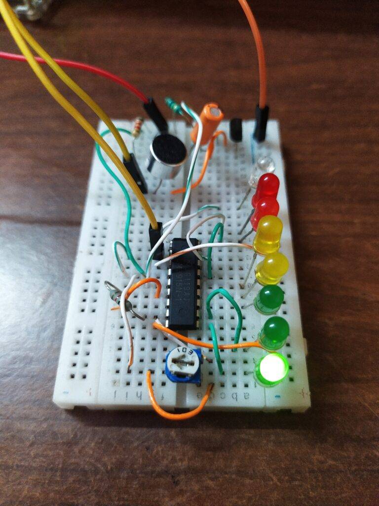
What is an RGB VU Meter?
A VU (volume unit) meter is a device used for displaying the signal level in audio equipment. Here we are using LEDs of different colors to represent how loud the sound is. The green LEDs are for low audio signals, Yellow for moderate, and red LEDs for the high audio signals. The rise and fall time of the current in the circuit is very fast.
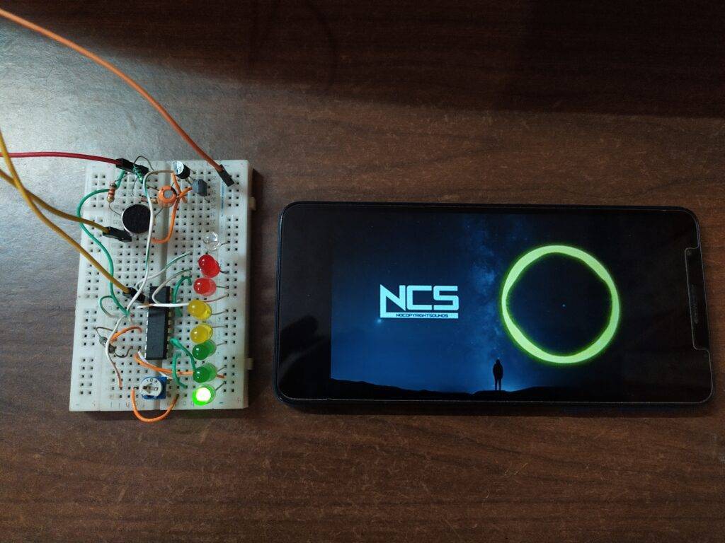
When the music is loud all the LEDs will glow as shown below.

You can adjust the brightness of the LEDs and the peak level by rotating the preset that is connected with the circuit. Do read more articles on basic ic projects written by us.
Components Required
| LM3915 ic | |
| LEDs of three different colors | BUY LINK |
| connecting wires | BUY LINK |
| breadboard | BUY LINK |
| 1K-ohm variable resistor | BUY LINK |
| 9 volt battery | BUY LINK |
| AUX cable and a mobile phone | |
| 1K-ohm resistor | BJUY LINK |
RGB VU Meter Circuit Diagram
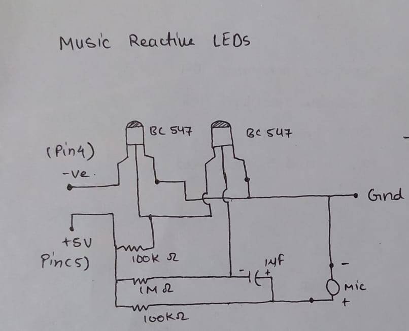
NOTE: You can connect an AUX cable with your mobile and then connect it with the ic pins. If you want to connect a mic with the circuit so that it can take input from it then make a new circuit with a mic and connect the positive wire of the circuit with pin 5 and the negative wire of the circuit with pin 4.
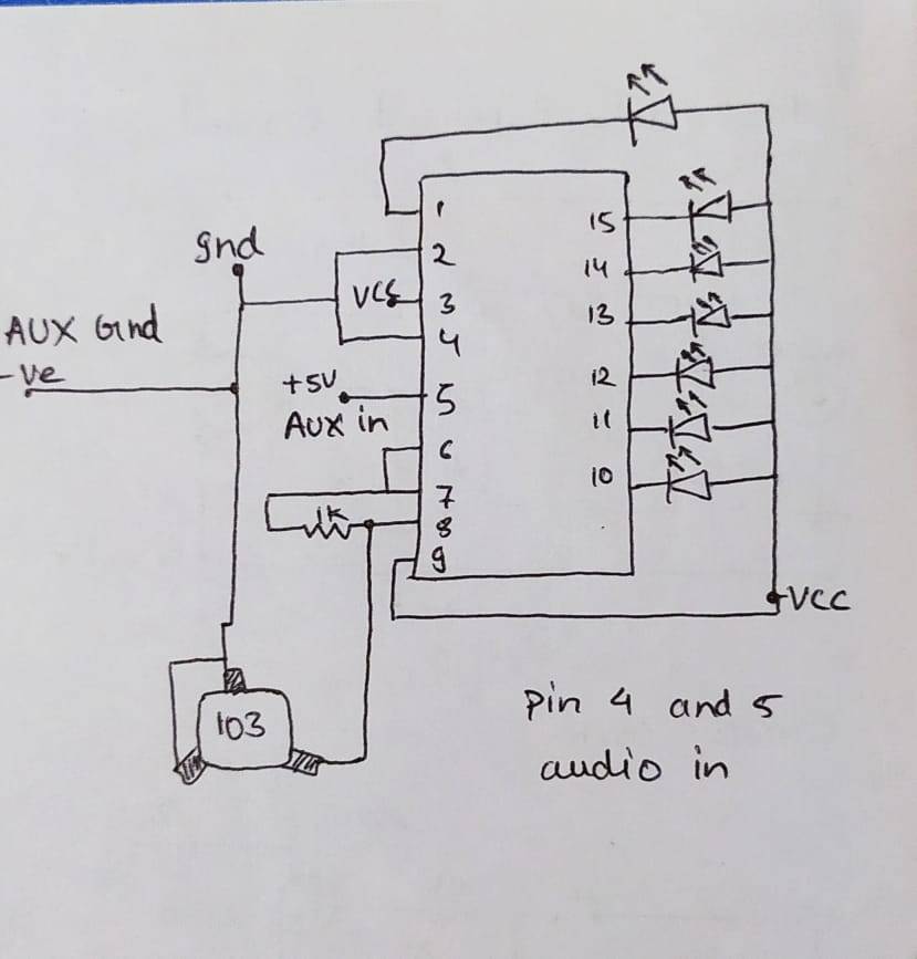
Connect the positive legs of all the LEDs of different colors together and then connect them with the positive rail. Join pin 9 and pin 3 of the ic with the positive rail. Attach the negative leg of the last LED to pin number 1 as shown. Now connect the negative legs of the LEDs with pin numbers 10, 11, 12, 13, 14, 15, 16, 17, 18 one by one. Join pin 2 and 4 with each other and then with the negative rail. Similarly, join pins 6 and 7 with each other and then with pin 8 via a 1K-ohm resistor. Now take a preset (103) and connect its middle pin with the side pin and then with the negative rail. Join the remaining pin of the preset with pin 8 of the ic. Take an AUX cable and connect its ground wire with pin 4 of the ic and other wire with pin 5 of the ic.
Let’s test it
Complete all the connections and then connect a 9 volts battery to the circuit. The LEDs start glowing level-wise depends on the electric signals that the ic receives.
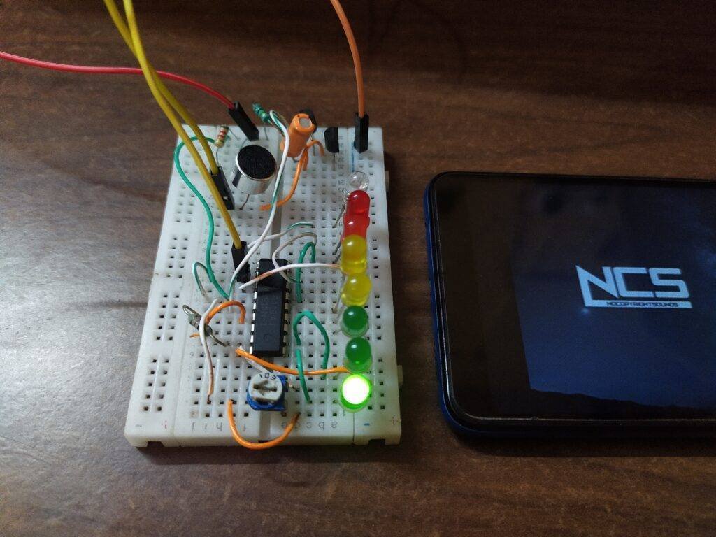
Now try to make this project on your own so that you will understand it better. If you have any quarries regarding this then ping us in the comments section below. Also, check our tutorials on Arduino and Raspberry Pi.
HAPPY LEARNING!