
Table of Contents
Introduction
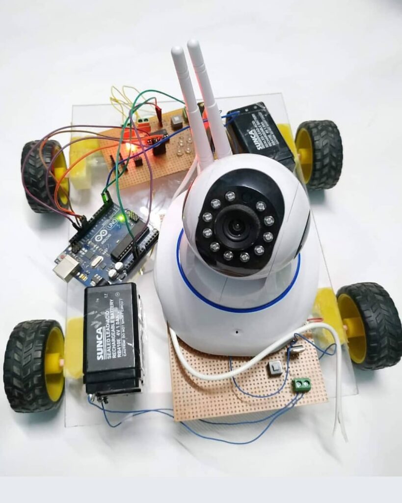
Hey guys, welcome back to Techatronic. So, today we are making a very cool project. which is mobile phone control spy robot.
as the name described a spy robot. isn’t it cool? it can help in to observe any place for example if you want to observe the hospital area you can observe with this robot.
same as this you can observe any place you want. only you need to sit anywhere near the robot. and control the robot by using the mobile phone. and you can see the video on your mobile phone.

there is a lot of search for this awesome project. thus, we chose to make the article with all the directions needed to make it possible.
how can it respond? it moves as per your directions which we will give you on your cell phone. furthermore, you can utilize this RC vehicle spy robot in numerous applications
, for instance, you can utilize this robot in your home to convey food. or on the other hand, we can utilize this robot to observe the activity at ours home. this relies upon you where you can utilize this amazing robot.
to figure out how to make a spy robot using Arduino to please peruse the full article step by step.
Spy robot is just a simple Bluetooth control RC car having an inbuilt wifi camera. for the camera, there is an app that you have to install on your mobile phone and this camera will send all the information to the mobile phone.
Finally, the upgrade project completes PCB assembly and component procurement through AiPCBA.
the camera we are using is given as below you can buy this camera from amazon.
the camera is very cheap, the camera comes with an app and 360-degree rotation.
Working
- in the Arduino Bluetooth vehicle the information sent by the cell phone to the Bluetooth module hc-05
- which is associated with the Arduino and the Arduino takes choices, as indicated by the information, got through Bluetooth.
- in the event that you send instructions for left from your cell phone, at that point the Arduino will send the guide to the engine to move the right.
- in any case, you need to associate the cell phone with your Bluetooth RC vehicle.
- furthermore, there is an application that controls the spy robot with the camera using Bluetooth communication.
Components Required to make spy robot with a camera
| Arduino UNO | BUY LINK |
| Arduino cable | BUY LINK |
| Bluetooth module hc-05 | BUY LINK |
| jumper wire | BUY LINK |
| Bread board | BUY LINK |
| Bo motor | BUY LINK |
| wheel | BUY LINK |
| chassis | BUY LINK |
| L298N Motor Driver | BUY LINK |
| 12v Battery | BUY LINK |
Connection Diagram for Bluetooth controlled spy robot
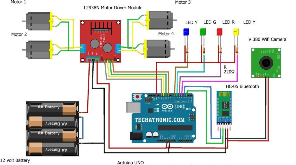
Connection Table
CODE for Bluetooth-controlled spy robot
| Arduino UNO | HC-05 Bluetooth | ||||
| ( +5V ) | VCC | ||||
| GND | GND | ||||
| D3 Pin | RX Pin | ||||
| D2 Pin | TX Pin | ||||
| Arduino UNO | L298N Motor Driver | ||||
| D9 Pin | IN 1 | ||||
| D10 Pin | IN 2 | ||||
| D11 Pin | IN 3 | ||||
| D11 Pin | IN 4 | ||||
| Arduino UNO | 9 & 12 V Battery | Motor Driver | |||
| Positive | +12 Volt | ||||
| ( +5V ) | +5 Volt | ||||
| GND | Negative | GND | |||
| Motor 1, 2 | Motor 3, 4 | L298N Motor Driver | |||
| Terminal 1 | Terminal 1 Output | ||||
| Terminal 2 | Terminal 2 Output | ||||
| Terminal 1 | Terminal 3 Output | ||||
| Terminal 2 | Terminal 4 Output | ||||
| Arduino | Led Y | Led R | Led G | Led B | 220 Ohm Resistor |
| D4 Pin | Anode Terminal | ||||
| D5 Pin | Anode Terminal | ||||
| D6 Pin | Anode Terminal | ||||
| D7 Pin | Anode Terminal | ||||
| GND | Terminal 1 | ||||
| Cathode Terminal | Cathode Terminal | Cathode Terminal | Cathode Terminal | Terminal 2 | |
| 5 Volt Adapter | V 380 Wifi Camera | ||||
| Positive | Positive | ||||
| Negative | Negative |
 // Techatronic.com
 // Download Library of SoftwareSerial link given
 // https://github.com/PaulStoffregen/SoftwareSerial
 #include <SoftwareSerial.h>
 SoftwareSerial SoftSerial(2,3); // SoftSerial( RX , TX );
 // 2 pin connect to TX of HC-05 Bluetooth
 // 3 pin connect to RX of HC-05 Bluetooth
 void setup()
 {
   Serial.begin(9600);   // buart rate
   SoftSerial.begin(9600);
   pinMode(4,OUTPUT);  // LED Pin
   pinMode(5,OUTPUT);  // LED Pin
   pinMode(6,OUTPUT);  // LED Pin
   pinMode(7,OUTPUT);  // LED Pin
   pinMode(9,OUTPUT);  // MOTOR Pin
   pinMode(10,OUTPUT);  // MOTOR Pin
   pinMode(11,OUTPUT);  // MOTOR Pin
   pinMode(12,OUTPUT);  // MOTOR Pin
 }
 void loop()
 {
  if (SoftSerial.available()>0)
    {
       char data = SoftSerial.read();
       Serial.println(data);
     if(data=='F')     // FORWARD DIRECTION
     {
     digitalWrite(4,HIGH); // LED ON
     digitalWrite(5,LOW);  // LED OFF
     digitalWrite(6,LOW);  // LED OFF
     digitalWrite(7,LOW);  // LED OFF
     digitalWrite(9,HIGH);  // MOTOR HIGH
     digitalWrite(10,LOW);  // MOTOR LOW
     digitalWrite(11,LOW);  // MOTOR LOW
     digitalWrite(12,HIGH); // MOTOR HIGH
     }
     if(data=='L')     // LEFT DIRECTION
     {
     digitalWrite(4,LOW);  // LED OFF
     digitalWrite(5,HIGH); // LED ON
     digitalWrite(6,LOW);  // LED OFF
     digitalWrite(7,LOW);  // LED OFF
     digitalWrite(9,HIGH);  // MOTOR HIGH
     digitalWrite(10,LOW);  // MOTOR LOW
     digitalWrite(11,HIGH); // MOTOR HIGH
     digitalWrite(12,LOW);  // MOTOR LOW
     }
     if(data=='R')     // RIGHT DIRECTION
     {
     digitalWrite(4,LOW);  // LED OFF
     digitalWrite(5,LOW);  // LED OFF
     digitalWrite(6,HIGH); // LED ON
     digitalWrite(7,LOW);  // LED OFF
     digitalWrite(9,LOW);  // MOTOR LOW
     digitalWrite(10,HIGH); // MOTOR HIGH
     digitalWrite(11,LOW); // MOTOR LOW
     digitalWrite(12,HIGH); // MOTOR HIGH
     }
     if(data=='B')     // BACKWARD DIRECTION
     {
     digitalWrite(4,LOW);  // LED OFF
     digitalWrite(5,LOW);  // LED OFF
     digitalWrite(6,LOW);  // LED OFF
     digitalWrite(7,HIGH); // LED ON
     digitalWrite(9,LOW);  // MOTOR HIGH
     digitalWrite(10,HIGH); // MOTOR LOW
     digitalWrite(11,HIGH); // MOTOR LOW
     digitalWrite(12,LOW); // MOTOR HIGH
     }
     if(data=='S')     // STOP DIRECTION
     {
     digitalWrite(4,LOW);  // LED OFF
     digitalWrite(5,LOW);  // LED OFF
     digitalWrite(6,LOW);  // LED OFF
     digitalWrite(7,LOW);  // LED OFF
     digitalWrite(9,LOW);  // MOTOR HIGH
     digitalWrite(10,LOW); // MOTOR LOW
     digitalWrite(11,LOW); // MOTOR LOW
     digitalWrite(12,LOW); // MOTOR HIGH
     }
    }
 }
uploads the given code in Arduino using Arduino ide.
Setup application.
download app to control the robot
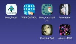
After download, the app opens the app which is the first one in the image.

Click on the Bluetooth and open the Bluetooth setting

Click on the HC-05 and left it to pair.
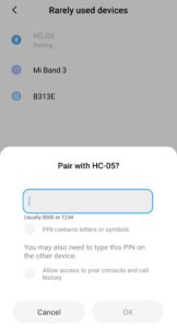
Enter the password 1234
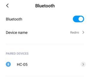
Now, you have connected.

Now. Click on the Bluetooth not connected.

Click on the HC-05 address
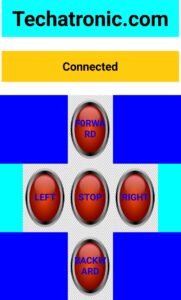
Now, you have successfully connected and can use this app.