Table of Contents
Introduction
Hey guys, we are back with another interesting post. Do you want to make an LED chaser circuit? Well if yes then you are at the right place. In this article,
we are going to make an LED chaser circuit using 4017 ic and 555 timer ic. We are also sharing the circuit diagram and detailed steps to make this project. You can also read more articles on Arduino and Raspberry Pi.

Description
- Before starting to make the circuit we suggest you go through the pin diagrams of both the ic’s so it is easier for you to identify the correct pins.
- The 555 timer ic which we use here is generating a square wave signal which is the input to the clock pin of the 4017 ic.
- In this 555 led chaser project, both the ic’s are working together to drive the LEDs one after another so that it looks like the LEDs are chasing each other.
- You can use this circuit for decoration purposes like you can see these kinds of fancy lights in the cafe, malls, or Diwali decoration lights.
- The pins of 4017 ic that we are used for connecting the LEDs are the output pins.
- One signal is high at a time and the remaining keeps low.
- You can connect up to ten LEDs at a time in this circuit because the out pins are ten only.
- You can also control the speed of the chasing LED using the potentiometer that we use in this project.
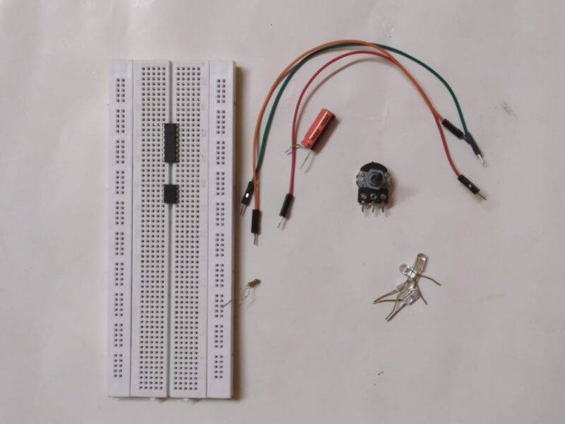
LED Chaser Components Required

| 555 timer ic | |
| 4017 ic | |
| Resistor 10K ohms | BUY LINK |
| Variable resistor 100K ohms | BUY LINK |
| Capacitor 10 uF | BUY LINK |
| LEDs | BUY LINK |
| Connecting wires | BUY LINK |
| Breadboard | BUY LINK |
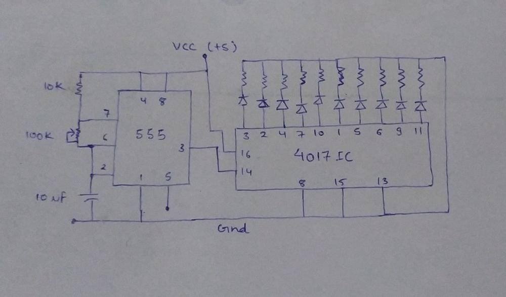
LED Chaser Circuit

- Place 6 LEDs on the breadboard and connect the negative pins of all the LEDs to the negative rail of the breadboard.
- Take a 555 timer ic and connect its pin 7 with pin 8 via a 10K resistor.
- Join pins 4 and 8 together.
- Connect the 100K variable resistor between pins 6 and 7 of the ic.
- Join pins 2 and 6 together.
- Now take a 10 uF capacitor and connect its positive leg with pin 2 of the ic and the negative leg with the negative rail of the breadboard.
- Join pin 1 to the negative rail too.
- As you know that pin 3 of the 555 timer ic is for output, so connect it with pin 14 of the 4017 ic.
- Connect pin 8 with the positive rail of the breadboard.
- Now let’s see the connections for the 4017 ic.
- Join pins 8, 13, and 15 with the negative rail.
- Connect pins 3, 2, 4, 7, 10, and 1 with the positive legs of the LEDs.
- Your LED chaser circuit is now complete and ready for use.
Let’s Test the Circuit

We hope that you liked this project and understand how the circuit works. Now try to make it on your own. If you are facing any difficulties during making this project then do let us know in the comments section given below. Also, check out more projects on Arduino and IoT made by us.
Thanks for reading.
