
How to make Gas leakage detector using Arduino
Welcome to the Techatronic guys, in this article we are going to make Gas leakage detector using Arduino that is basically used for LPG detection. we can use this in our kitchen. if someone forgets to off the burner or any leakage happened from the gas pipe. so this sensor alarm can easily identify and make you aware of the leakage. so this is a very useful alarm and easy to make. you need only Arduino buzzer and the display is always optional. you can save yourself with this cheap alarm. there is much more alarm without programming but this is the accurate one. it has quite a good accuracy as you can see in the given video in the last of the post. bookmark our website to learn more basic and intermediate level project. our last project fingerprint security alarm is very good as you can see on our website. in this article, we will work on the Arduino and learn Arduino with our Arduino introduction article.

How does it work?
Our Gas leakage detector using Arduino is very responsive and attractive also because we are using the OLED display to display the information of the system to the screen. as we are using the MQ 6 sensor here which is the gas reactive sensor. it has a coil that reacts to the gas and varies the data. whenever it senses LPG gas the value of the output of the sensor will start the change that you can see in the video as I am going to share with you. the sensor can give both output analog as well as digital. as we are working here for the accuracy because we can take the chance so we will use the analog one. analog is more precise than digital. so whenever the sensor comes in the contact with the gas it changes the value and sends it to the Arduino. Arduino processes the value and compares it with the given threshold value in the database. and if the condition gets true the alarm start and if the condition is not true the alarm will not start. we also added some characters into the OLED display which is interesting. so see the full video Gas leakage detector using Arduino given in the last portion of the post.
The OLED display is the most attractive display in the projects right now. this project will show the value of the sensor and its status. there are two statuses one is ALL WELL and another is WARNING. there is a buzzer and led also for the notification. as the system detects gas it will start to make sound via a buzzer and the Red LED will start to glow.
LPG gas leakage detector using Arduino components required
Required components:-
- MQ 6 –BUY LINK
- Arduino Nano –BUY LINK
- OLED –BUY LINK
- PCB –BUY LINK
- Buzzer –BUY LINK
- RGB LED –BUY LINK
- Wires -BUY LINK
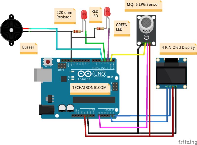
Circuit diagram for LPG gas leakage detector using Arduino:-
You Can Buy All Components To Together –BUY LINK

Fritzing circuit diagram
Code for gas leakage detector using Arduino
#include <SPI.h>
#include <Wire.h>
#include <Adafruit_GFX.h>
#include <Adafruit_SSD1306.h>

#define SCREEN_WIDTH 128 // OLED display width, in pixels
#define SCREEN_HEIGHT 32 // OLED display height, in pixels

// Declaration for an SSD1306 display connected to I2C (SDA, SCL pins)
#define OLED_RESET     4 // Reset pin # (or -1 if sharing Arduino reset pin)
Adafruit_SSD1306 display(SCREEN_WIDTH, SCREEN_HEIGHT, &Wire, OLED_RESET);

#define NUMFLAKES     10 // Number of snowflakes in the animation example

#define LOGO_HEIGHT   16
#define LOGO_WIDTH    16
static const unsigned char PROGMEM logo_bmp[] =
{ B00000000, B11000000,
  B00000001, B11000000,
  B00000001, B11000000,
  B00000011, B11100000,
  B11110011, B11100000,
  B11111110, B11111000,
  B01111110, B11111111,
  B00110011, B10011111,
  B00011111, B11111100,
  B00001101, B01110000,
  B00011011, B10100000,
  B00111111, B11100000,
  B00111111, B11110000,
  B01111100, B11110000,
  B01110000, B01110000,
  B00000000, B00110000 };


void setup() {
  pinMode(A0, INPUT);
   pinMode(2, OUTPUT);
  pinMode(3, OUTPUT);
  pinMode(4, OUTPUT);
  Serial.begin(9600);

  // SSD1306_SWITCHCAPVCC = generate display voltage from 3.3V internally
  if(!display.begin(SSD1306_SWITCHCAPVCC, 0x3C)) { // Address 0x3C for 128x32
    Serial.println(F("SSD1306 allocation failed"));
    for(;;); // Don't proceed, loop forever
  }

  // Show initial display buffer contents on the screen --
  // the library initializes this with an Adafruit splash screen.
  display.display();
  delay(2000); // Pause for 2 seconds

  // Clear the buffer
  display.clearDisplay();

  // Draw a single pixel in white
  display.drawPixel(10, 10, SSD1306_WHITE);

  // Show the display buffer on the screen. You MUST call display() after
  // drawing commands to make them visible on screen!
  display.display();
  delay(2000);
  // display.display() is NOT necessary after every single drawing command,
  // unless that's what you want...rather, you can batch up a bunch of
  // drawing operations and then update the screen all at once by calling
  // display.display(). These examples demonstrate both approaches...

 //testdrawline();      // Draw many lines

  //testdrawrect();      // Draw rectangles (outlines)

  //testfillrect();      // Draw rectangles (filled)

 // testdrawcircle();    // Draw circles (outlines)

  //testfillcircle();    // Draw circles (filled)

  //testdrawroundrect(); // Draw rounded rectangles (outlines)

  //testfillroundrect(); // Draw rounded rectangles (filled)

  //testdrawtriangle();  // Draw triangles (outlines)

 // testfilltriangle();  // Draw triangles (filled)

  //testdrawchar();      // Draw characters of the default font

 // testdrawstyles();    // Draw 'stylized' characters

//  testscrolltext();    // Draw scrolling text

 // testdrawbitmap();    // Draw a small bitmap image

  // Invert and restore display, pausing in-between
  display.invertDisplay(true);
  delay(1000);
  display.invertDisplay(false);
  delay(1000);
  pinMode(A0, INPUT);
  Serial.begin(9600);

 // testanimate(logo_bmp, LOGO_WIDTH, LOGO_HEIGHT); // Animate bitmaps
}


void loop() {
  // put your main code here, to run repeatedly:


int p= analogRead(A0);
Serial.println(p);
display.clearDisplay();
  display.setTextSize(2); // Draw 2X-scale text
  display.setTextColor(SSD1306_WHITE);

   if(p>= 260 )

   {display.setCursor(5, 8);
    display.println(p);
  display.setCursor(60, 5);
   display.setTextSize(1);
  display.println(F("WARNING"));


display.setCursor(60, 20);
   display.setTextSize(1);
  display.println(F("GAS LEAKAGE"));
digitalWrite(2, LOW);
  digitalWrite(3, HIGH);
  digitalWrite(4, HIGH);
  display.display();
  delay(50);
   }
else


{
   display.setCursor(5, 8);

   display.println(p);
  display.setCursor(60, 12);
   display.setTextSize(1);
  display.println(F("ALL WELL"));
  display.display();
  digitalWrite(2, HIGH);
  digitalWrite(3, LOW);
  digitalWrite(4, LOW);
  delay(50);


  }

}
  #define XPOS   0 // Indexes into the 'icons' array in function below
#define YPOS   1
#define DELTAY 2
Download Adafruit GFX library from GitHub