Table of Contents
Introduction
In this article, we will be making an Arduino Digital Clock project using the DS1307 RTC module.
We will be using a 16×2 LCD display with an I2C interface to display the time and some other components. If you want to make your own DIY project,
you can use the basic structure of this project. We have already made various Arduino projects, Embedded projects, and Arduino tutorials on our website. You can visit them if you are new to the world of electronics and Arduino.
What is Arduino Digital Clock?
- This Digital clock uses the DS1307 RTC Module as its brain for its time calculation.
- The Arduino reads the signal from the module and displays the time on an LCD display.
- One can customize this to make an integrated alarm clock, Arduino Timer for time-based application projects, and many more.
- This module is very cheap and common and can be found easily in the market. this can also be used in many other DIY projects also.
- We can use different types of displays such as 7-segment displays, OLED displays, LED matrix, RGB LEDs, etc.
- to display the time. You can make an Automatic pet Feeder, Automatic Light, time-based plant watering system, and much more using this. This reduces the manual stress on us.
How Does It Work?
- The RTC Module uses a crystal oscillator to output signals at regular intervals.
- It also has a Built-In battery which acts as a backup for the RTC module in case if the power supply interrupts to prevent resetting of the module.
- the module is capable of counting seconds, minutes, hours, days, weeks, months, and years. Arduino uses the I2C communication protocol to send data to the LCD display,
- which we are using here to display the time. The display updates every second to tell the most accurate time since the module is much accurate to tell the time.
- The module is capable of running for more than 5 years continuously without affecting the count in time. this is possible because of the in-built cell.
Components Required
| Arduino UNO | BUY LINK |
| DS1307 RTC Module | BUY LINK |
| I2C LCD Module | BUY LINK |
| 16×2 LCD Display | BUY LINK |
| Jumper Wires | BUY LINK |
| Breadboard | BUY LINK |
| Arduino UNO Cable | BUY LINK |
You can buy all components together-BUY LINK
Components Table/buy table
You can buy the whole components from the given link we have to share the amazon link. from where you can get a good discount on the components.
Arduino Digital Clock Circuit Diagram
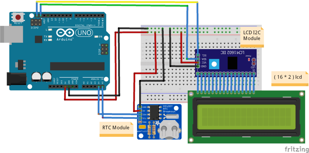
Connection Table
| Arduino UNO | DS1307 RTC Module |
| ( +5V ) | VCC |
| GND | GND |
| A4 Pin ( SDA ) | SDA Pin |
| A5 Pin ( SCL ) | SCL Pin |
| Arduino UNO | I2C Module |
| ( +5V ) | VCC |
| GND | GND |
| A4 Pin ( SDA ) | SDA Pin |
| A5 Pin ( SCL ) | SCL Pin |
| 16*2 LCD Display | I2C Module |
| 16 Pin-connected | 16 Pin-connected |
Since we are using an I2C based Display controller, we need to use only 4 wire connections for the display.
Arduino Digital Clock Arduino Code
NOTE- You need to install the three libraries LiquidCrystal_I2C.h, Wire.h, and DS1307.h which can be downloaded from HERE into your Arduino IDE before uploading the code.
 #include <DS3231.h> // RTC LIBRARY
 #include <Wire.h> // WIRE LIBRARY
 #include <LiquidCrystal_I2C.h> //I2C LIBRARY
 LiquidCrystal_I2C lcd(0x27,16,2);
 // Init the DS3231 using the hardware interface
 DS3231 rtc(SDA, SCL);
 void setup()
 {
 lcd.init();
 lcd.backlight();
 // Setup Serial connection
 Serial.begin(9600);
 // Initialize the rtc object
 rtc.begin();
 // The following lines can be uncommented to set the date and time
 // rtc.setDOW(FRIDAY); // Set Day-of-Week to SUNDAY
 // rtc.setTime(9, 58, 0); // Set the time to 12:00:00 (24hr format)
 //rtc.setDate(6, 12, 2019); // Set the date to January 1st, 2014
 }
 void loop()
 {
 // Send Day-of-Week
 Serial.print(rtc.getDOWStr());
 Serial.print(" ");
 // Send date
 Serial.print(rtc.getDateStr());
 Serial.print(" -- ");
 // Send time
 Serial.println(rtc.getTimeStr());
 lcd.setCursor(0,0);
 lcd.print(rtc.getDateStr ());
 lcd.setCursor(0,1);
 lcd.print(rtc.getTimeStr ());
 lcd.setCursor(9,1);
 lcd.print(rtc.getDOWStr());
 // Wait one second before repeating :)
 delay (1000);
 }
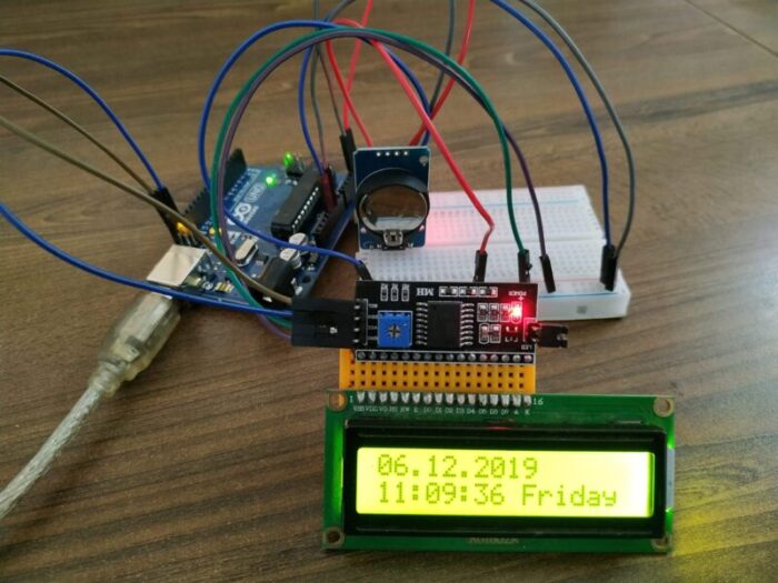
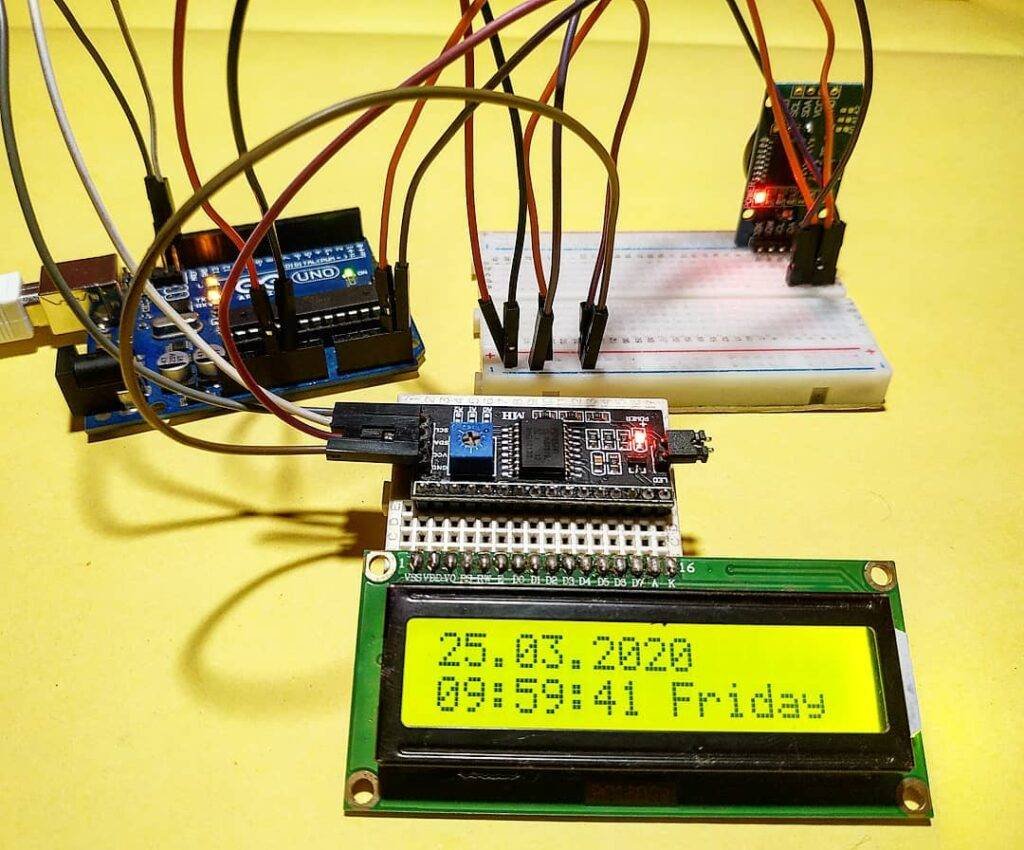
Once the uploading of code is complete, LCD Display will be able to show the Time as per the code uploaded. I hope you found this guide helpful in making the project. If you have any doubts, you can put them in the comment section below.
Final Output on Display